
Spinal Plate

a technology of spinal plates and screws, applied in the field of spinal plates, can solve the problems of reducing the stability of the spinal plate, limiting the number of screws, and affecting the safety of patients, so as to increase the safety and/or stability, and improve the positive patient outcom

Active Publication Date: 2013-03-07
GLOBUS MEDICAL INC
View PDF20 Cites 276 Cited by
  • Summary
  • Abstract
  • Description
  • Claims
  • Application Information

AI Technical Summary

Benefits of technology

The patent is about a new type of bone plate that improves safety and stability during bone surgeries. This results in better patient outcomes and other benefits.

Problems solved by technology

Current spinal plates, however, suffer from one or more limitations.
For example, there are often situations and size restrictions that limit the number of screws that can be used in a design or surgery.
Fewer screws results in lower stability of the plate.
There is a risk, however, that the sharp features may puncture or damage blood vessels, nerves, or other delicate anatomical structures during placement.
There is also a difficulty for the surgeon to determine how well the plate will rest on the bone surface without first inserting the spikes into the bone.
Blocking set screws, however, do not prevent the bone screws from rotating.
Loose bone screws reduce the stability of the bone-plate interface, thereby reducing the chance of a successful fusion procedure.

Method used


Image

  • Spinal Plate
  • Spinal Plate
  • Spinal Plate

Examples


Embodiment Construction

[0044]The aspects of the disclosure and the various features and advantageous details thereof are explained more fully with reference to the non-limiting aspects and examples that are described and / or illustrated in the accompanying drawings and detailed in the following description. It should be noted that the features illustrated in the drawings are not necessarily drawn to scale, and features of one aspect may be employed with other aspects as the skilled artisan would recognize, even if not explicitly stated herein. Descriptions of well-known components and processing techniques may be omitted so as to not unnecessarily obscure the aspects of the disclosure. The examples used herein are intended merely to facilitate an understanding of ways in which the disclosure may be practiced and to further enable those of skill in the art to practice the aspects of the disclosure. Accordingly, the examples and aspects herein should not be construed as limiting the scope of the disclosure, ...


PUM

PropertyMeasurementUnit
lengthaaaaaaaaaa
lengthaaaaaaaaaa
lengthaaaaaaaaaa

Abstract

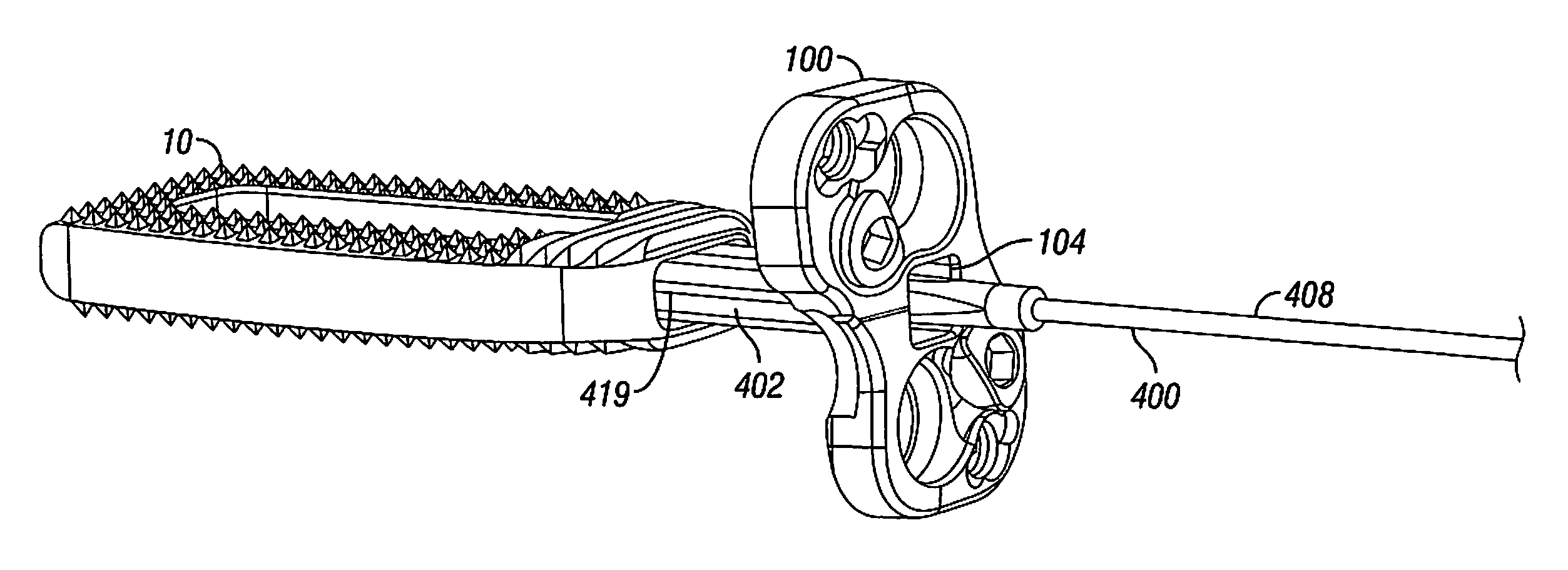
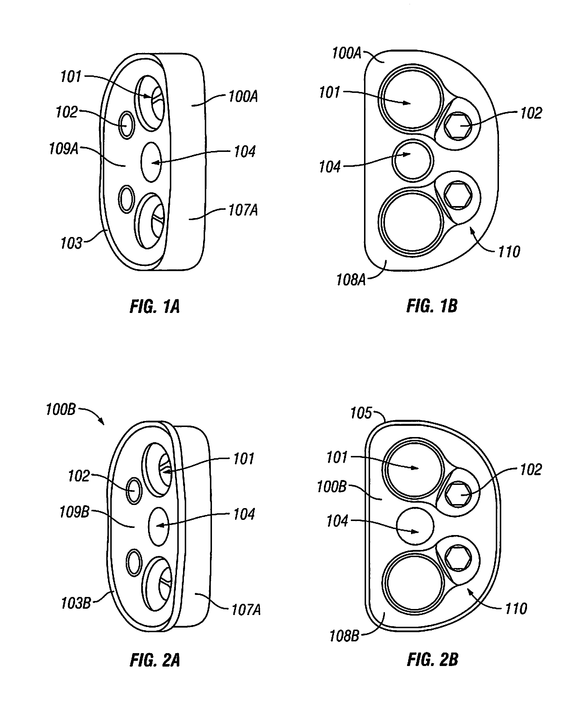
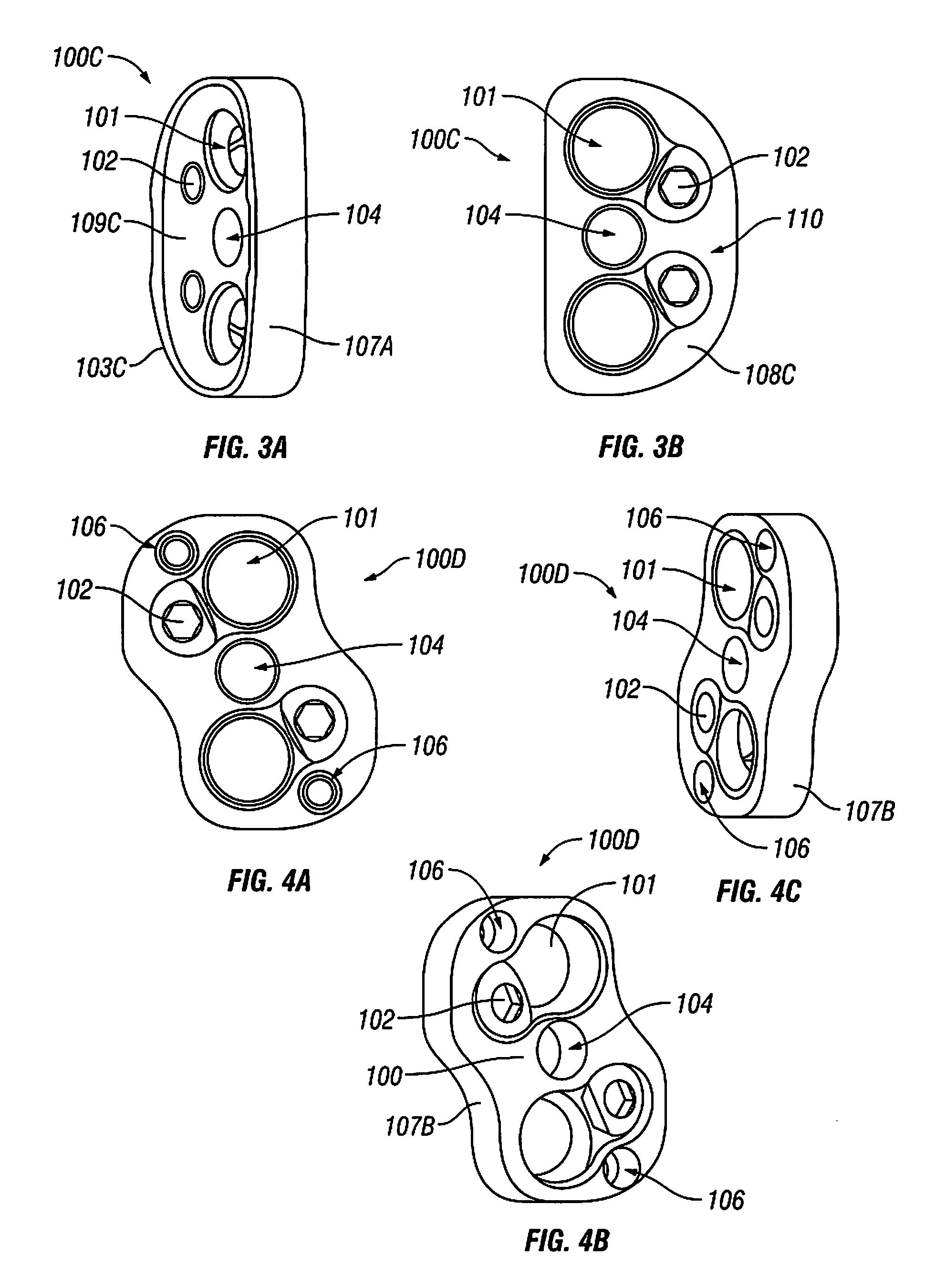
Spinal plates with additional features to improve the stability of the interface between the plate and the underlying bone. A bone plate may include one or more sharp ridges along the periphery of its underside. When attached to bone, the ridge digs into the bone and increases stability. A bone plate may alternatively or additionally include one or more holes for optional spikes, which may be inserted once the plate is attached to the bone. By separating the spikes and including them as an optional component, the plate may enhance stability while reducing or eliminating the chance of the spike injuring the patient. Furthermore, bone screws may incorporate alternating notches and ridges into the head of the screw. The notches and ridges may interface with a set screw, thereby preventing rotation and loosening of the screw.

Description

CROSS REFERENCE TO RELATED APPLICATIONS[0001]This application is a continuation-in-part application of U.S. patent application Ser. No. 13 / 226,092 filed on Sep. 6, 2011, which is incorporated by reference herein in its entirety.BACKGROUND OF THE DISCLOSURE[0002]1. Field of the Disclosure[0003]The disclosure relates to devices for immobilizing two or more vertebrae relative to one another to promote fusion of the vertebrae. The devices and improvements described herein may also be used with other types of bone plates or instrumentation.[0004]2. Related Art[0005]Adjacent vertebrae may be surgically joined together in a fusion procedure. The procedure may join two (bi-level) or more (multi-level) vertebrae. During the surgery, the vertebrae are fixed in position relative to one another with a plate or other instrumentation, and a bone graft is placed between the vertebrae. The bone graft will promote new bone growth between the vertebrae, and eventually the bones will grow together, wh...

Claims


Application Information

Patent Timeline
Patent Type & Authority Applications(United States)
IPC IPC(8): A61F2/44
CPCA61F2/447A61B17/809A61F2002/30433A61F2002/30509A61F2002/30576A61F2002/30578A61F2002/30607A61F2002/30772A61F2002/30785A61F2002/30787A61F2002/308A61F2002/30843A61F2002/30904A61F2002/3098A61F2002/4475A61F2310/00407A61F2310/00796A61F2002/30482A61B17/7059A61B17/92A61B2017/922A61B17/8042A61B17/808A61F2/4611A61F2220/0016A61F2002/30507A61F2/3094A61F2002/30593A61F2/46A61F2/4455A61F2002/4615A61F2002/4622
Inventor PETERSHEIM, SAMUELAGARD, RYAN
Owner GLOBUS MEDICAL INC
Learn More