
Slit tube locking longeron

a technology of slit tube and locking tube, which is applied in the direction of construction elements, towers, buildings, etc., can solve the problems of inability to address the inadequacies of patents, the lack of longitudinal and torsional rigidity of hollow members, and the inability to achieve the necessary longitudinal and torsional rigidity, etc., to achieve the effect of improving the alignment and interlocking of features

Active Publication Date: 2013-03-14
COMPOSITE TECH DEV
View PDF1 Cites 29 Cited by
  • Summary
  • Abstract
  • Description
  • Claims
  • Application Information

AI Technical Summary

Benefits of technology

The patent text describes a method for making a deployable member with interlocking lateral protrusions along one or both edges. This involves modifying the edges of a longeron to implement the protrusions, which will interlock upon deployment. The method may also involve removing material from the edges to create the protrusions, and deforming the protrusions out-of-plane to improve feature alignment and interlocking upon deployment. The technical effect of this patent is to provide a reliable and effective mechanism for interlocking parts in a deployable member, making it easier to assemble and use.

Problems solved by technology

Presently known structures that are field deployable from a stored state to an operable state suffer from disadvantages in their operable state caused by the features which make them so readily deployable.
While flexibility lends itself well to compact storage, and hence portability, in the stored state, flexibility is often not a desired feature for the structure in the deployed state.
Because of the slit, these hollow members suffer from a lack of necessary longitudinal and torsional rigidity.
The aforementioned patents do not disclose means of addressing these inadequacies.

Method used


Image

  • Slit tube locking longeron
  • Slit tube locking longeron
  • Slit tube locking longeron

Examples


Embodiment Construction

[0024]The ensuing description provides exemplary embodiments only, and is not intended to limit the scope, applicability or configuration of the disclosure. Rather, the ensuing description of the exemplary embodiments will provide those skilled in the art with an enabling description for implementing one or more exemplary embodiments. It being understood that various changes may be made in the function and arrangement of elements without departing from the spirit and scope of the invention as set forth in the appended claims.

[0025]Specific details are given in the following description to provide a thorough understanding of the embodiments. However, it will be understood by one of ordinary skill in the art that the embodiments may be practiced without these specific details. For example, systems, processes, and other elements in the invention may be shown as components in block diagram form in order not to obscure the embodiments in unnecessary detail. In other instances, well-known...


PUM

PropertyMeasurementUnit
Temperatureaaaaaaaaaa
Lengthaaaaaaaaaa
Forceaaaaaaaaaa

Abstract

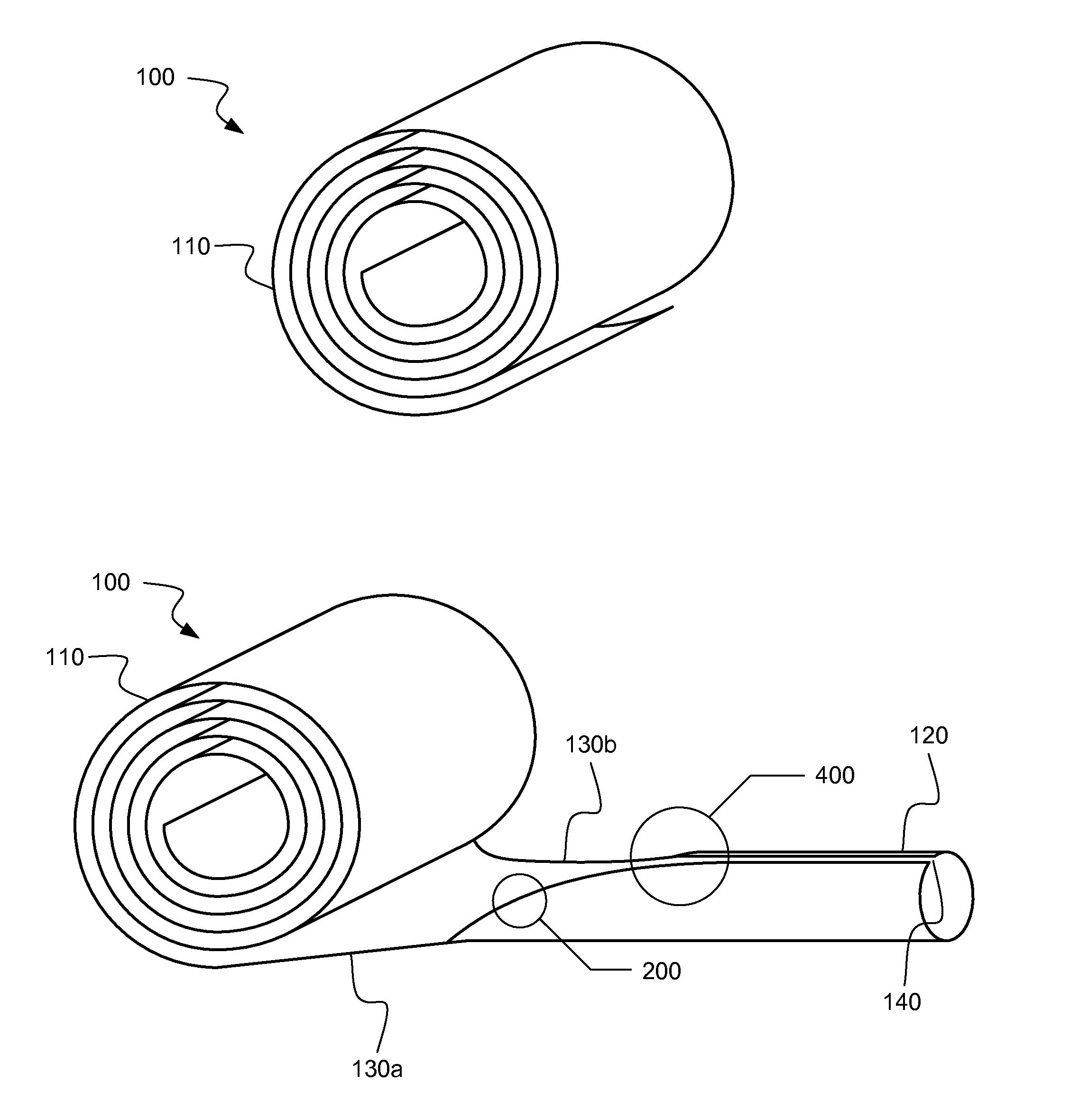
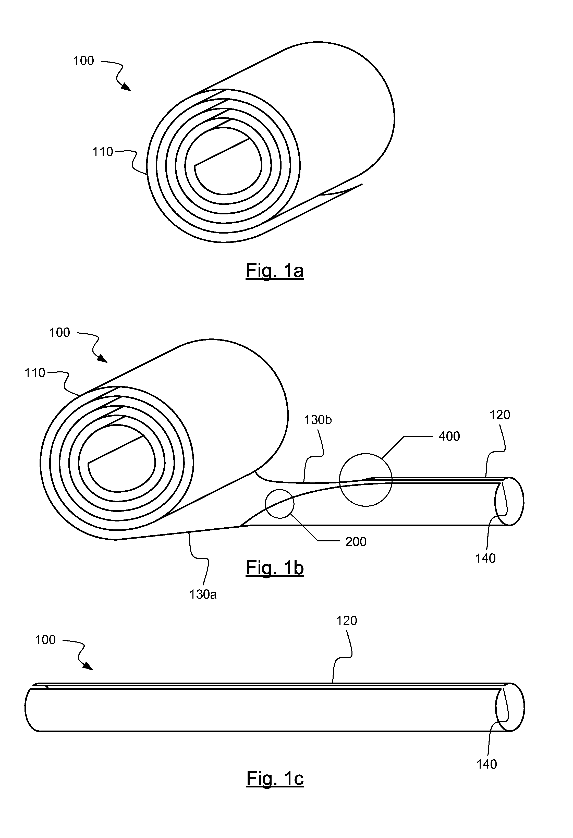
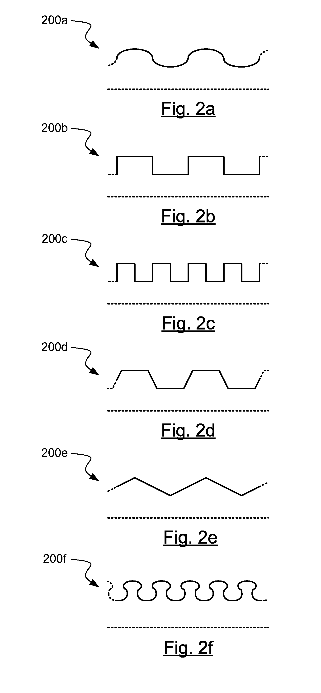
According to the invention, an extendable member is disclosed. The extendable member may include a structure having a first state and a second state. The structure may be deformable between the first state and the second state. In the first state the structure may include a compact form. In the second state the structure may include a hollow longeron having a slit along the entire length of the hollow longeron. One or both longitudinal edges along the slit of the hollow longeron may have lateral protrusions. The lateral protrusions of a longitudinal edge may act in such a way with the other edge, and possibly its protrusions, to at least partially inhibit relative motion of the edges.

Description

CROSS-REFERENCES TO RELATED APPLICATIONS[0001]This application claims priority to Provisional U.S. Patent Application No. 61 / 534,151, filed Sep. 13, 2011, entitled “Slit Tube Locking Longeron,” the entire disclosure of which is hereby incorporated by reference, for all purposes, as if fully set forth herein.BACKGROUND OF THE INVENTION[0002]This invention relates generally to deployable structures. More specifically, the invention relates to structural members which are deployable from a compact initial state.[0003]Presently known structures that are field deployable from a stored state to an operable state suffer from disadvantages in their operable state caused by the features which make them so readily deployable. Primary among these features is flexibility. While flexibility lends itself well to compact storage, and hence portability, in the stored state, flexibility is often not a desired feature for the structure in the deployed state. This is especially true where in the deplo...

Claims


Application Information

Patent Timeline
IPC IPC(8): E04H12/00B23P17/00B29C53/02E04H12/34B29C53/84
CPCB29C67/0014B29C67/0044Y10T29/49826Y10T29/49865F16S5/00
Inventor TAYLOR, ROBERTTURSE, DANAADAMS, LARRY G.REAVIS, MARKRICHARDSON, DOUG
Owner COMPOSITE TECH DEV
Learn More