Rivet

a technology of rivets and screws, applied in the direction of fastening means, screws, sheet joining, etc., can solve the problems of unsuitable connection of existing tuk rivets, and achieve the effects of simplifying manufacturing difficulty, reducing centering requirements, and simple mounting die structur

Pending Publication Date: 2020-10-22
PENN ENG & MFG CORP
View PDF2 Cites 0 Cited by
  • Summary
  • Abstract
  • Description
  • Claims
  • Application Information

AI Technical Summary

Benefits of technology

[0011]2. When riveting with a rivet of the present invention, a flat die can be used as the mounting die. That is, the cavity of the lower die uses a simple plane and no special shape is required, which makes the structure of the mounting die simple and at the same time reduces the centering requirement between the riveting device and the mounting die (as shown in FIG. 1, the riveting device needs to be centered with the embossment of the lower die when riveting with an existing rivet).
[0012]3. The main body and the core part of the present invention can be formed separately, which can simplify the manufacture difficulty for the mold of the main body and improve the service life of the mold. Since adopting a separate structure enables the main body and the core part to be manufactured independently, the core part can be manufactured into a relatively complicated structure to enhance the interlocking ability of the rivet.
[0013]4. The main body and the core part can be formed of same or different materials, which is beneficial to save material cost. Besides, the main body and the core part can be made of aluminum, which can eliminate the electroplating process on the rivet, thereby reducing production cost. The weight of the rivet can also be greatly reduced to achieve a lightweight design.
[0014]5. The rivet of the present invention has a skirt section on the core part, so that during the riveting process of the rivet, not only the interlocking function of the core part with the first work piece is increased, but also the skirt section can further push the second end of the main body to fold outwardly, thereby enhancing the interlocking level between the second end of the main body portion and the work piece, and greatly improving the tensile resistance at the riveting point of the rivet.

Problems solved by technology

Therefore, the existing tuk rivets are not suitable for the connection with the high sealing requirements such as waterproofing.

Method used


Image

  • Rivet
  • Rivet
  • Rivet

Examples


Embodiment Construction

[0031]The technical solutions in the embodiments of the present invention will be clearly and completely described in the following with reference to the accompanying drawings in the embodiments of the present invention. It is apparent that the described embodiments are only a part of the embodiments of the present invention, rather than all the embodiments. All the other embodiments that can be obtained by a person of ordinary skill in the art according to the embodiments of the present invention without creative work are within the protection scope of the present invention.

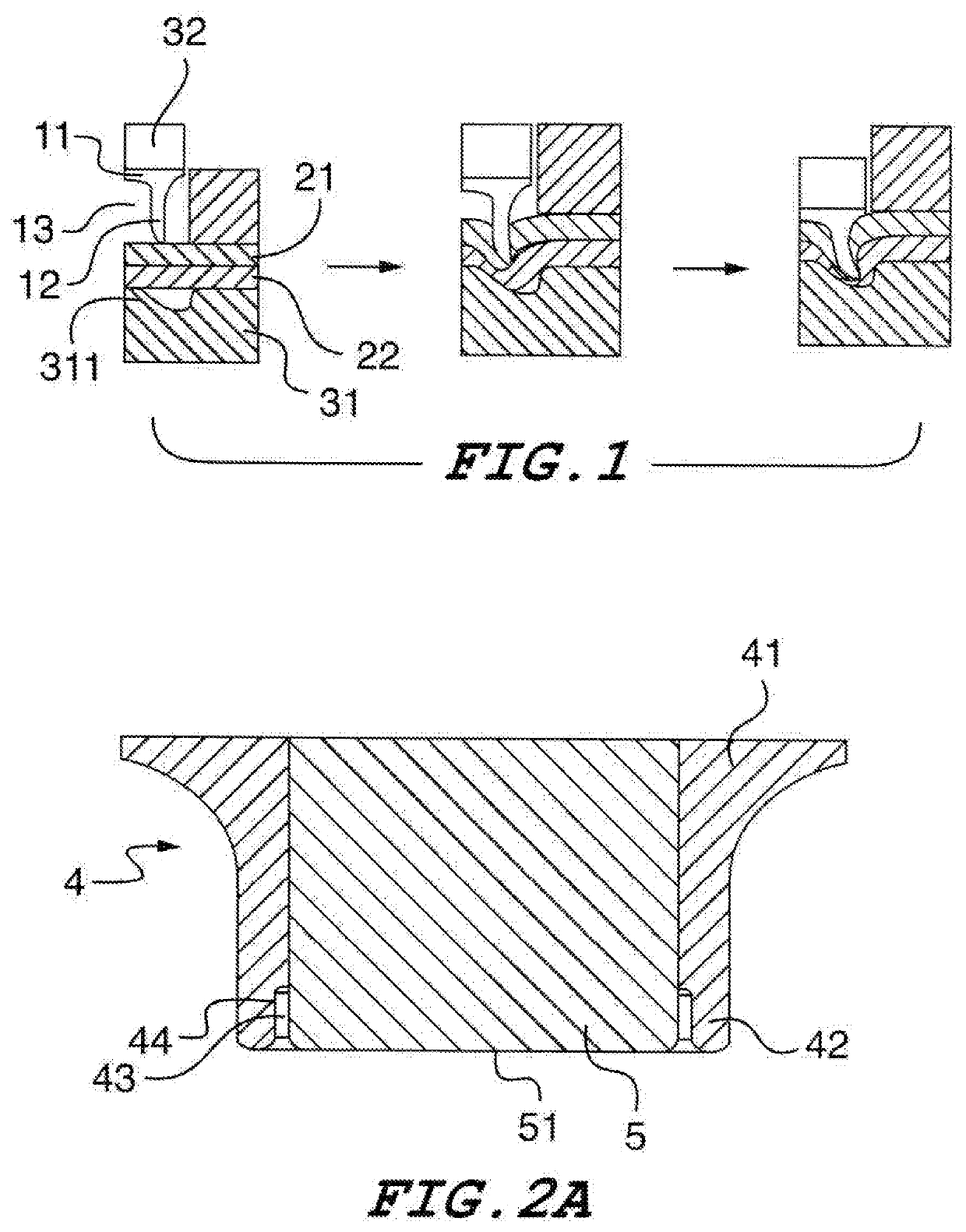
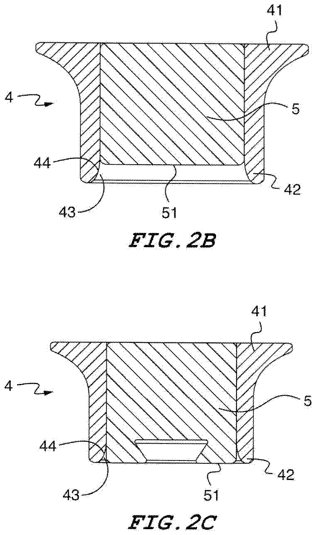
[0032]FIG. 2A illustrates a rivet for riveting work pieces according to the embodiment, the rivet comprises a main body 4 and a core part 5.

[0033]The main body 4 comprises a first end 41 and a second end 42 opposite to the first end 41. The main body 4 further comprises a lateral wall 44 disposed at the second end 42 and circumferentially extending around the main body 4.

[0034]The core part 5 is disposed at the ...


PUM

PropertyMeasurementUnit
thicknessaaaaaaaaaa
diameteraaaaaaaaaa
outer diameteraaaaaaaaaa

Abstract

The present rivet invention has a main body comprising a first end and a second end opposite to the first end, wherein the main body further comprises a lateral wall disposed at the second end and circumferentially extending around the main body; and a core part disposed at the second end of the main body and contained inside the lateral wall of the main body, wherein the core part has an end surface for pressing against at least an end surface of one of the work pieces when the rivet is being operated to rivet the work pieces, to allow materials of the work pieces flow outwardly of the core part. An accommodation space is formed between the core part and the lateral wall to receive materials of the work pieces flowing into the space and deform outwardly at least a portion of the lateral wall of the main body.

Description

TECHNICAL FIELD[0001]The present application generally relates to fastener technology, and particularly to a rivet for fastening to sheets of material together.[0002]The present non-provisional patent application is related to Chinese patent application 325739749 filed on Apr. 16, 2019 and Chinese patent application number 325739750 filed on Apr. 16, 2019, priority from which is hereby claimed.BACKGROUND[0003]When a rivet is used for riveting thin plates, the riveting position is discretionary because a pre-punching on the riveted plates is not required. Furthermore, the rivet has no waste core after the riveting, and thus it is material saving, easy to operate, and highly efficient. Therefore, a tuk rivet is suitable for mass assembly line work, and is very widely applied.[0004]FIG. 1 is a riveting schematic diagram of an existing tuk rivet. The existing rivet is generally a hollow rivet, which includes a head portion 11 and a foot portion 12 formed as a single part. The thickness ...

Claims


Application Information

Patent Timeline
Patent Type & Authority Applications(United States)
IPC IPC(8): F16B19/10F16B5/04
CPCF16B5/04F16B19/1027B21J15/025
Inventor SUN, QIANGCAI, SHENGBAOWU, YONGDUAN, DAPENGYAN, XIAOFEI
Owner PENN ENG & MFG CORP
Why Eureka
Try Eureka