Adaptor connector and electric connector assembly

A technology of transfer connectors and electrical connectors, which is applied to the parts, connections, and electrical components of the connecting device, and can solve problems such as small distance, difficulty in aligning two PCB boards, and insufficient voltage resistance

Active Publication Date: 2019-04-09
CHINA AVIATION OPTICAL-ELECTRICAL TECH CO LTD
View PDF2 Cites 5 Cited by
  • Summary
  • Abstract
  • Description
  • Claims
  • Application Information

AI Technical Summary

Problems solved by technology

[0003] The existing electrical connector assemblies used between two PCB boards are all two-piece plug-in structures. The plug and socket are plugged together, requiring a maximum lateral offset of 0.15mm. If the offset is out of tolerance, it will The distance between the signal conductor and the ground conductor of the plug and socket is too small, resulting in problems such as insufficient withstand voltage capability
Therefore, the current electrical connectors used for connection between PCBs have very strict requirements on the alignment accuracy between the two PCB boards, but in the actual application process, the alignment between the two PCB boards is more difficult.

Method used


Image

  • Adaptor connector and electric connector assembly
  • Adaptor connector and electric connector assembly
  • Adaptor connector and electric connector assembly

Examples


Embodiment Construction

[0048] Embodiments of the present invention will be further described below in conjunction with the accompanying drawings.

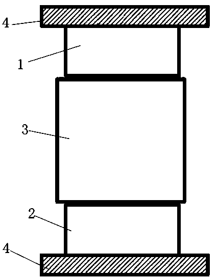
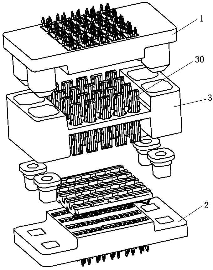
[0049] Specific embodiments of the electrical connector assembly of the present invention, such as Figure 1 to Figure 2 As shown, the electrical connector assembly includes three parts, namely a first connector 1 , a second connector 2 and a transition connector 3 . In this embodiment, since the first connector 1 and the second connector 2 have the same structure, they are collectively referred to as end connectors here.

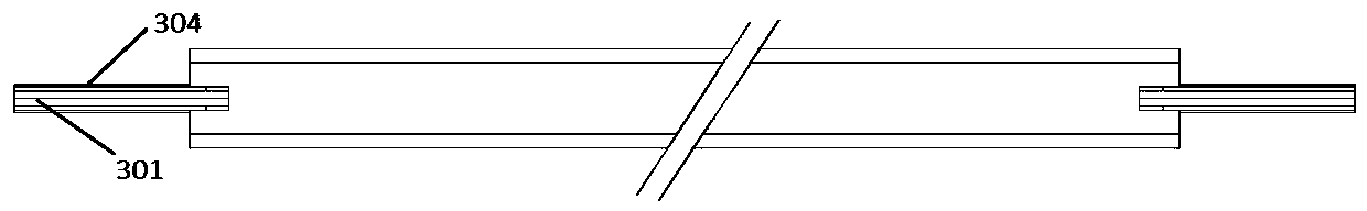
[0050] The transfer connector 3 includes a housing and a plurality of contact units installed in the housing. Each contact unit is provided as a module by itself. A plurality of mounting holes extending along the insertion direction are provided in the transfer connector housing. Each contact module 30 Correspondingly installed in the mounting hole, the inner cavity of the mounting hole is larger than the contact module to meet the flo...


PUM


Abstract

The invention provides an adaptor connector and an electric connector assembly. The electric connector assembly comprises a first connector, a second connector and the adaptor connector, wherein the adaptor connector comprises a shell and a contact unit installed inside the shell; the contact unit is provided with two inserted connection ends; an an-falling structure for limiting the contact unitinside the shell is arranged on the shell; the contact unit is installed inside the shell in a floating manner so as to move in the inserted connection direction and the direction vertical to the inserted connection direction. Due to the fact that the electric connector assembly comprises three parts such as the first connector, the second connector and a contact assembly, and the contact unit ofthe adaptor connector is installed inside the shell in the floating manner so as to move in the inserted connection direction and the direction vertical to the inserted connection direction, so that,during inserted connection, the offset of an inserted closing part can be reduced through the cooperation of two ends of the contact unit with the first connector and the second connector, so that possibility is provide for the miniaturization design of electric connector products and the transmission design of high-speed data.

Description

technical field [0001] The invention relates to a transfer connector and an electrical connector assembly. Background technique [0002] The electrical connector assembly is a commonly used connection device between two devices or components. In actual production and life, such as between the chassis module and the cabinet, between the battery box and the battery compartment or charging rack, and between two PCB boards. Encounter situations that require connection with electrical connector assemblies. Among them, the electrical connector components used to transmit signals between two PCB boards are mainly differential connector components, which have very strict requirements on signal transmission speed, transmission quality, and density. [0003] The existing electrical connector assemblies used between two PCB boards are all two-piece plug-in structures. The plug and socket are plugged together, requiring a maximum lateral offset of 0.15mm. If the offset is out of tolera...

Claims


Application Information

Patent Timeline
Patent Type & Authority Applications(China)
IPC IPC(8): H01R12/71H01R12/91H01R13/02H01R13/40H01R13/46H01R13/631H01R13/648H01R31/06
CPCH01R12/71H01R12/716H01R12/91H01R13/02H01R13/40H01R13/46H01R13/631H01R13/6315H01R13/648H01R13/665H01R24/00H01R31/06H01R12/7082H01R12/73H01R12/585H01R13/6658H01R13/6471H01R12/737H05K1/14H05K1/142H05K2201/10189H05K2201/10704H05K1/115H05K1/184H05K2201/10515H05K2201/10871H05K2201/10856H05K2201/10878
Inventor 袁俊峰马陆飞屈峰成
Owner CHINA AVIATION OPTICAL-ELECTRICAL TECH CO LTD
Why Eureka
Try Eureka