
Keyboard instrument

a keyboard and instrument technology, applied in the field of keyboard instruments, can solve the problems of affecting the intrinsic the deterioration of the internal sound quality of the acoustic piano, and the influence of the soundboard characteristics

Active Publication Date: 2013-03-14
YAMAHA CORP
View PDF22 Cites 23 Cited by
  • Summary
  • Abstract
  • Description
  • Claims
  • Application Information

AI Technical Summary

Benefits of technology

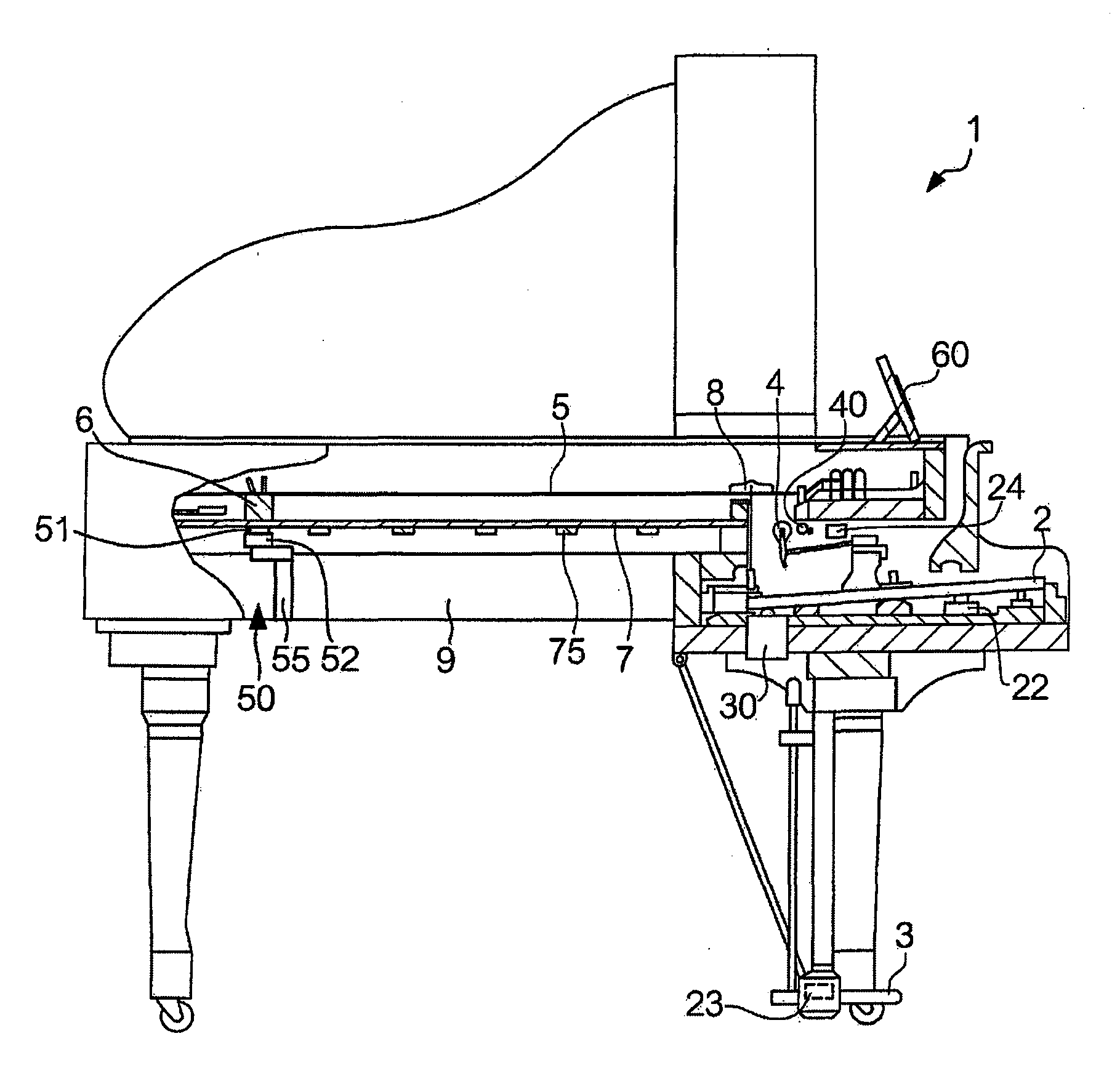
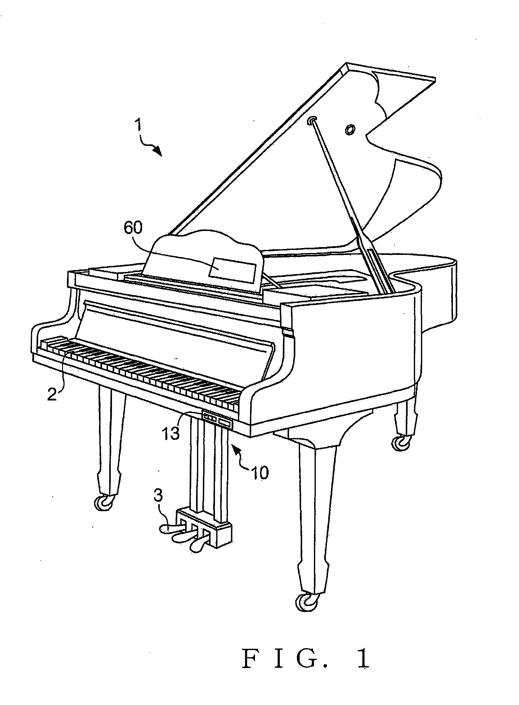
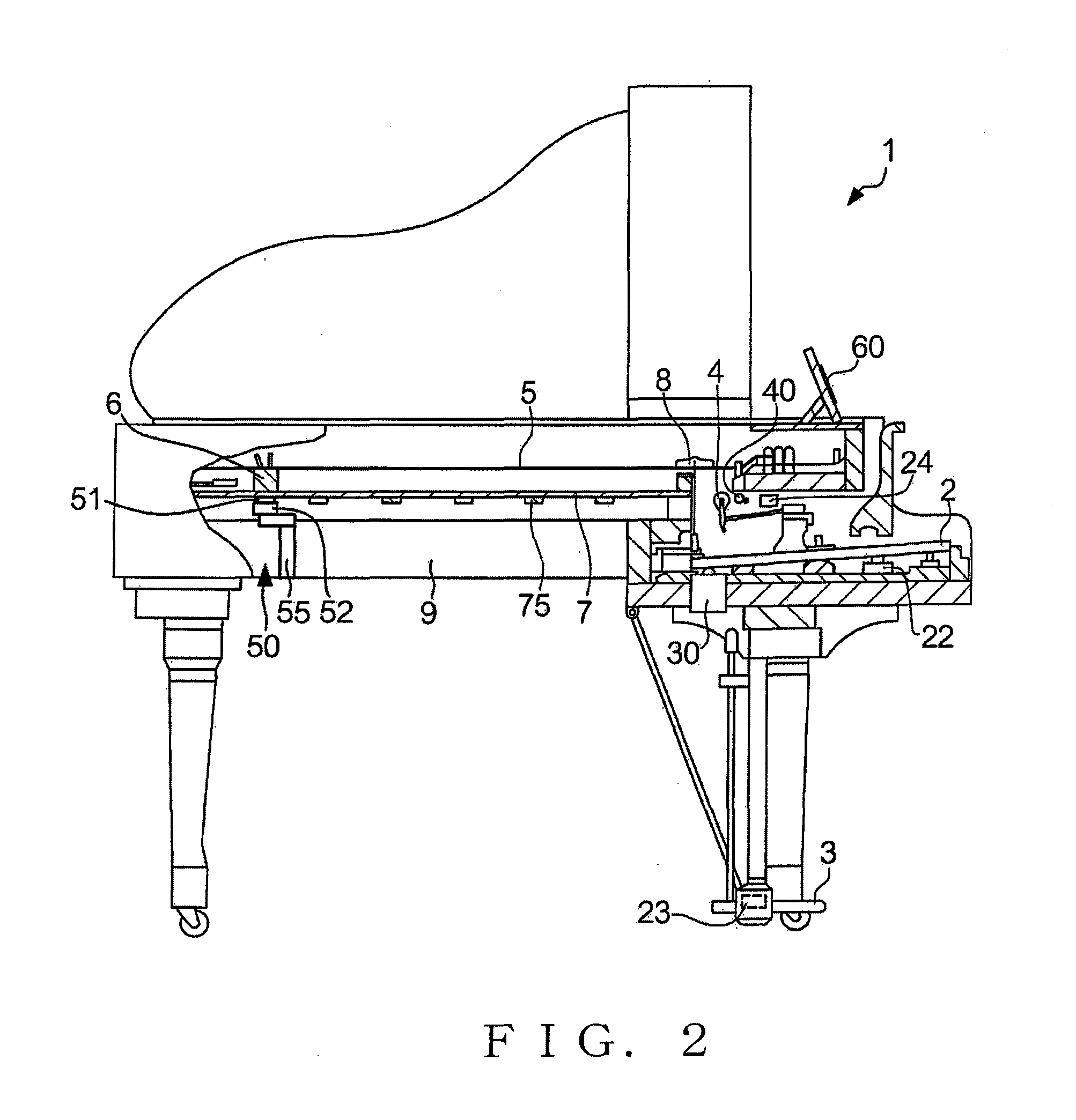
The present invention provides a keyboard instrument with a structure for exciting the soundboard without adversely affecting its vibration characteristics. The excitation unit includes vibration members connected to the soundboard and a heavier main body that generates at least one of attraction force and repulsion force to vibrate the vibration members. The supporting unit supports the main body so that less or no load is applied to the soundboard, minimizing the load on the soundboard. This allows the instrument to generate acoustic sounds unique to its design while enriching the overall acoustic sound. A controller can selectively control the generation of the acoustic sound based on the vibration of the soundboard or both the acoustic sound and the instrument's inherent sound. This expands the sound generation modes of the instrument, providing more diversity and flexibility in its sound output.

Problems solved by technology

As a result, an intrinsic sound quality of the acoustic piano deteriorates.
Thus, when the above-described preceding technology is applied to the acoustic piano, the vibration characteristics of the soundboard is changed due to an influence of the speaker so that the intrinsic sound quality of the acoustic piano is influenced and changed, which is a problem.

Method used


Image

  • Keyboard instrument
  • Keyboard instrument
  • Keyboard instrument

Examples


modification 1

[Modification 1]

[0118]Whereas the preferred embodiment of the vibration member 51 (connecting member 511) is completely separated from the yoke-holding unit 52, the vibration member 51 may be connected indirectly with the yoke-holding unit 52 or casing 524.

[0119]FIG. 14 is a cross-sectional view of excitation unit 50A to which modification 2 of the present invention is applied. The excitation unit 50A in the illustrated example includes a damper unit 53 configured to connect the connecting member 511 with the casing 524. The damper unit 53 is expanded and contracted following a vertical vibration of the connecting member 511 from the standard position where the voice coil 512 is not driven by the drive signal and no force is applied to the soundboard 7 by the connecting member 511. In the illustrated example, in a condition that the connecting member 511 is not yet connected to the soundboard 7 and is kept supported by only the damper unit 53, a height of the supporting unit 55 for ...

modification 2

[Modification 2]

[0121]Whereas the preferred embodiment of the grand piano 1 of the present invention has been described above as applied to a grand piano, it may be applied to an upright piano.

[0122]FIG. 15 is a view showing an inner construction of an upright piano 1B which employs modification 2 of the present invention is applied. In FIG. 15, elements of the upright piano 1B similar to the elements of the grand piano 1 are indicated by the same reference numerals as used for the grand piano 1 but each with suffix “B”. In the upright piano 1B too, the vibration member 51B in then excitation unit 50B is connected to the soundboard 7B, and the yoke-holding unit 52B is supported by the supporting unit 55B connected to the straight supporting column 9B.

[0123]FIG. 16 is a view explanatory of a positional arrangement of the excitation unit 50B according to the modification 2. In the illustrated example as well, the excitation unit 50B is connected to the soundboard 7B located between ri...

modification 3

[Modification 3]

[0124]Whereas, in the above-described preferred embodiment, the excitation unit 50 is supported by the supporting unit 55 so that no load except the vibration member 51 is applied to the soundboard 7, other weight than the vibration member 51 may be applied to. For example, the supporting unit 55 may support the excitation unit 50 in a state in which it is connected to the soundboard 7. Alternatively, an excitation unit may be attached directly to the soundboard 7 without existence of the supporting unit 55. A case where no supporting unit 55 exists will be described with reference to FIG. 17.

[0125]FIG. 17 is a side view showing a state in which an excitation unit 50C is directly mounted onto the soundboard 7 employing modification 3 of the present invention. The excitation unit 50C comprises a vibration member 51C and connecting members 54C. The vibration member 51C is connected to the soundboard 7 with the connecting member 54C such as a screw. The vibration member...


PUM


Abstract

In a predetermined sound generation mode, a drive signal having a frequency characteristic corresponding to an operated key is supplied to an excitation unit provided on a soundboard. In response to a mechanical vibration generated by the excitation unit, the soundboard is vibrated so as to generate an acoustic vibration sound corresponding to the operated key. The excitation unit is supported by a supporting unit such that less or no load of the excitation unit except a vibration member vibrated in response to the drive signal is applied to the soundboard. Thus, only a load of the vibration member which is a very light portion of the excitation unit is applied to the soundboard, thereby vibration characteristics of the soundboard being hardly affected. When a sound damping mode is selected, a stopper is permitted to prevent a hammer from striking a sounding body.

Description

BACKGROUND[0001]The present invention relates to a technology for enriching a sound (i.e., musical sound or tone) of an acoustic keyboard instrument.[0002]Usually, an electronic piano has no soundboard unlike an acoustic piano, because the electronic piano is configured to produce electronic sound from a speaker. However, Japanese patent application laid-open publication No. JP2008-292739A discloses a technology of mounting a soundboard on the electronic piano and installing speakers on the soundboard so that by exciting the soundboard with the speakers, a vibration sound is radiated from the soundboard. As a result, the electronic piano can produce not only electronic sounds but also enriched acoustic low-pitched sounds due to radiation of the vibration sounds from the soundboard. The above-mentioned patent literature also discloses that such a technology can be applied to not only the electronic piano but also a case where the acoustic piano is configured not to vibrate any string...

Claims


Application Information

Patent Timeline
Patent Type & Authority Applications(United States)
IPC IPC(8): G10C1/00
CPCG10C3/06G10H1/08H04R3/08G10H2210/271G10H1/32H04R7/045G10C1/00G10C3/20G10H2220/311G10H1/045G10C3/161G10C9/00G10C3/04G10C3/22
Inventor OHNISHI, KENTAMANTANI, ROKUROUTA
Owner YAMAHA CORP
Learn More