Power tool and suspension device for the power tool

a technology of power tools and suspension devices, applied in the field of power tools, can solve the problems of poor usability of tools, self-sustainable yoke, and inability to sustain the running loop,

Inactive Publication Date: 2013-03-14
MAKITA CORP
View PDF19 Cites 44 Cited by
  • Summary
  • Abstract
  • Description
  • Claims
  • Application Information

AI Technical Summary

Benefits of technology

[0020]With the configurations of the suspension devices according to the seventh and eighth aspects of the present invention, since the suspension device includes the ring and the ring retaining member, the ring is detachably mounted to the power tool in such a manner as to be movab

Problems solved by technology

However, according to this power tool equipped with the suspension device, since the yoke rotates around the circular loop and the bearing, the yoke is not self-sustainable.
Further, since the running loop is merely inserted into the yoke, the running loop is not self-sustainable.
Therefore, the user has to use both hands when he is hanging the power tool on the hook, which leads to poor usability of the tool.
Further, as the circular loop of the metallic yoke contacts the tool housing, relativel

Method used


Image

  • Power tool and suspension device for the power tool
  • Power tool and suspension device for the power tool
  • Power tool and suspension device for the power tool

Examples


Embodiment Construction

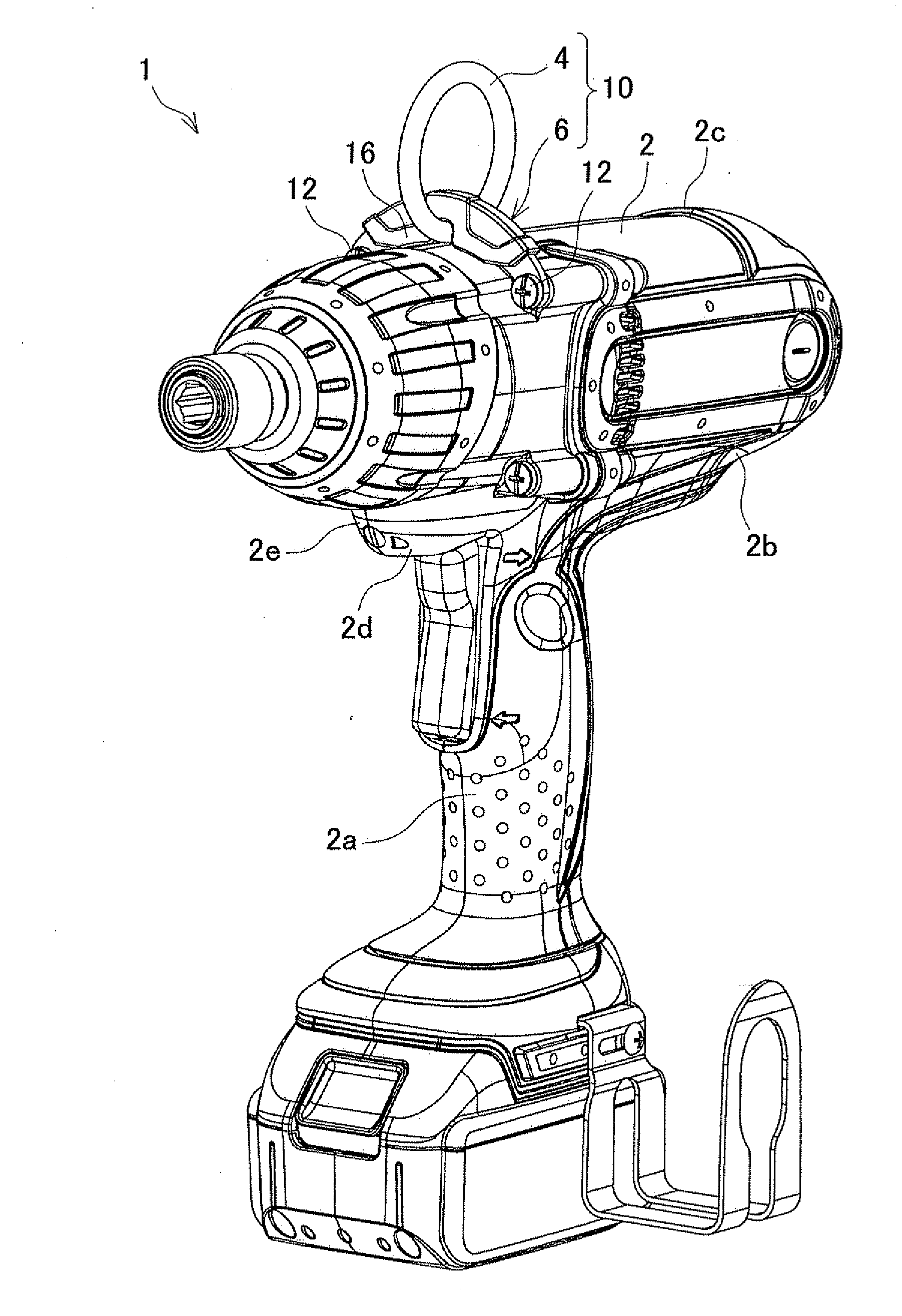
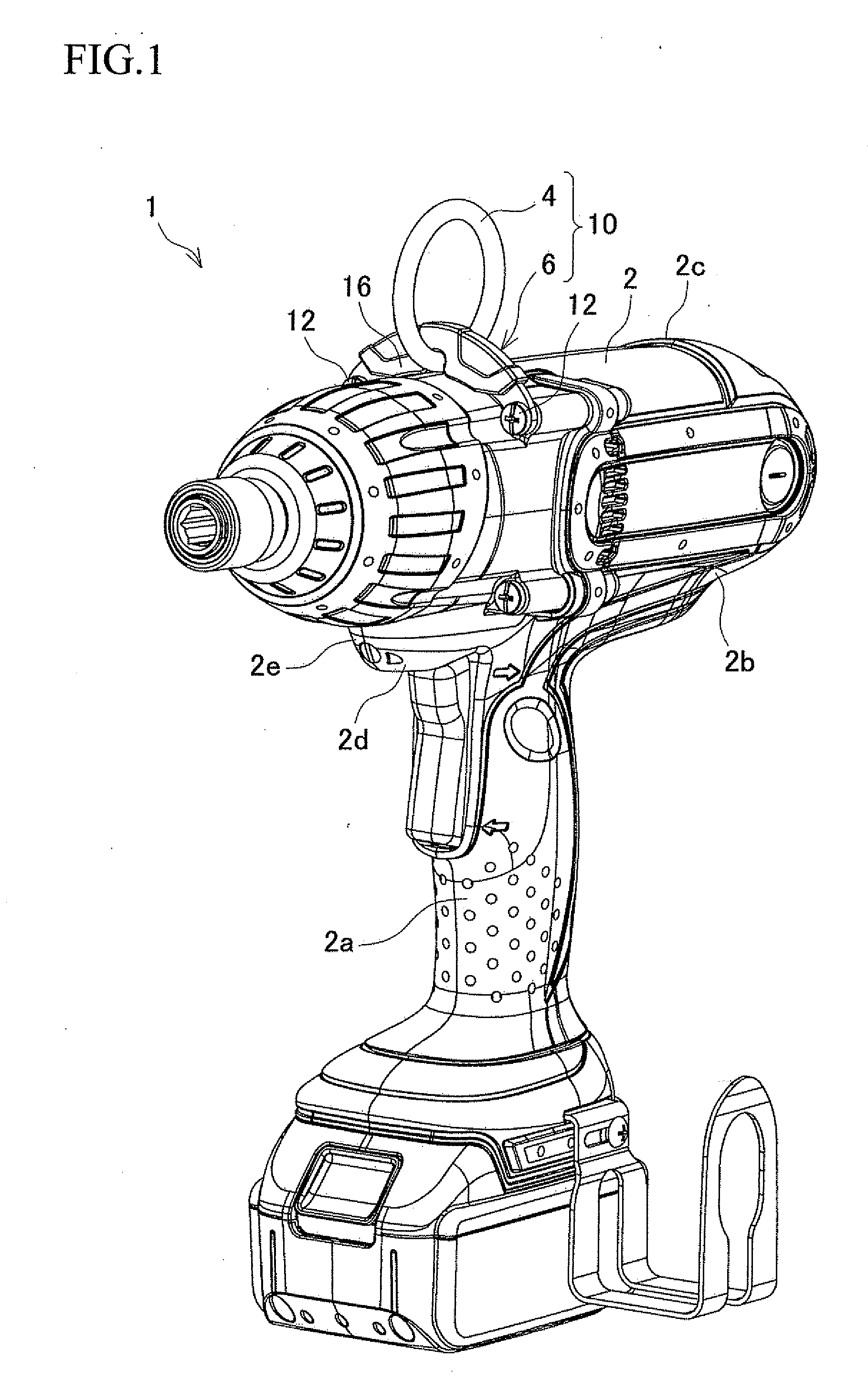
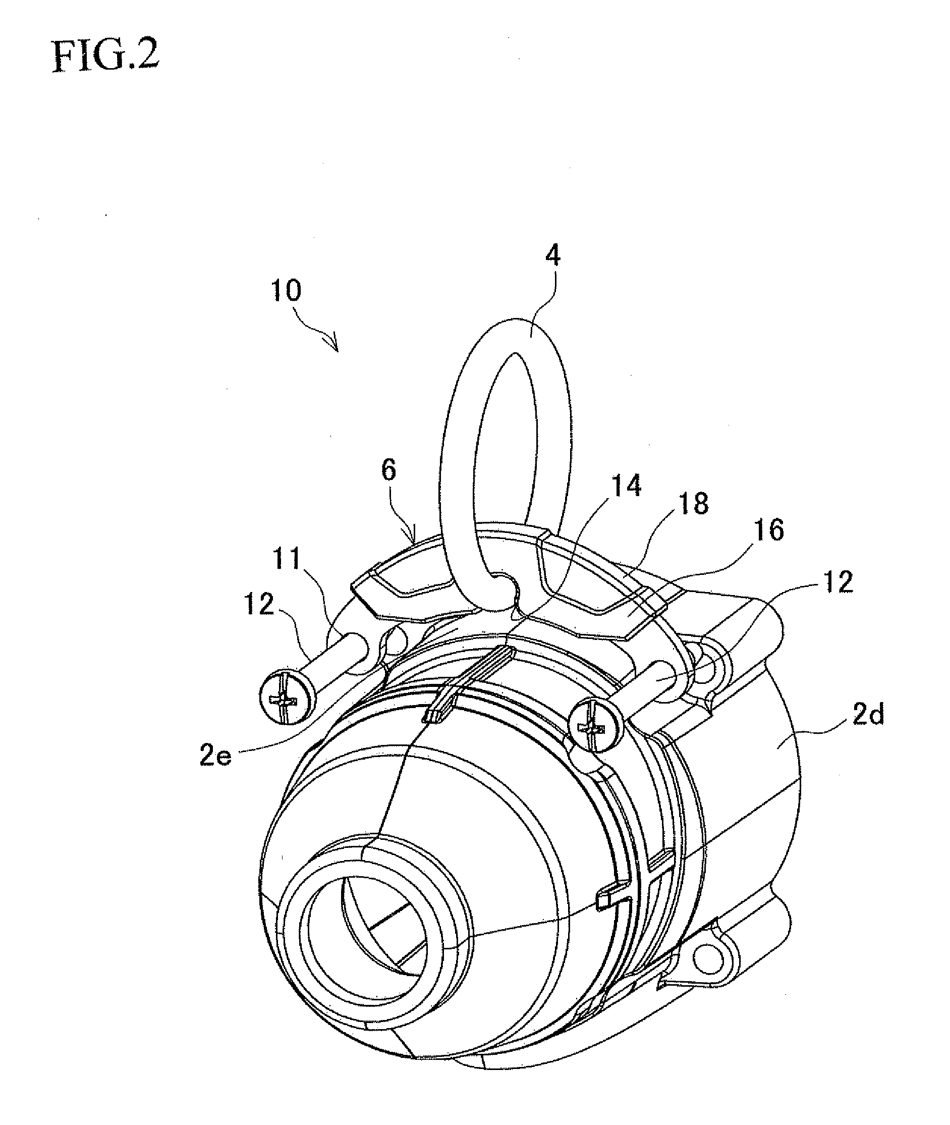
[0025]With reference to the accompanying drawings, one exemplary embodiment of the present invention will be described below. FIG. 1 is a perspective view of a rechargeable impact wrench as an example of a power tool. FIG. 2 is a partly exploded enlarged perspective view showing an upper front side of the rechargeable impact wrench.

[0026]As shown in FIG. 1, an impact wrench 1 includes a housing 2 having a grip 2a at a lower part of the housing 2. A suspension device 10 including a ring 4 and a bracket 6 is arranged at an upper center portion of the housing 2.

[0027]The suspension device 10 is arranged at the upper center portion of the housing 2 where an upward extension of the grip 2a and the upper part of the housing 2 intersect. In this exemplary embodiment, the ring 4 and the bracket 6 are arranged partially in a region of the intersecting portion. However, the ring 4 and the bracket 6 may partially cover the entire region of the intersecting portion. As an alternative, the whole...


PUM


Abstract

The suspension device includes a ring for hanging the power tool and a ring retaining member provided at an upper part of a housing of the power tool. The housing has a grip at a lower part thereof. The ring retaining member is configured such that the ring is movable between a standing position and a lying position and that the ring is retainable in the standing position.

Description

BACKGROUND OF INVENTION[0001]This application claims the benefit of Japanese Patent Application Number 2011-200967 filed on Sep. 14, 2011, the entirety of which is incorporated by reference.TECHNICAL FIELD[0002]The present invention relates to a power tool such as an electric power tool and an air tool, and a suspension device used for the power tool.BACKGROUND ART[0003]A power tool equipped with a suspension device as disclosed in Japanese Patent Application Laid-open No. 01-193183A is known in the art. The suspension device includes a yoke made of rigid metal wire, and a running loop or shackle to be inserted into the yoke. One end of the yoke is formed as a circular loop for surrounding a cylindrical portion of the tool housing, while the other end of the yoke is connected to a bearing at the rear end wall of the tool housing.[0004]However, according to this power tool equipped with the suspension device, since the yoke rotates around the circular loop and the bearing, the yoke i...

Claims


Application Information

Patent Timeline
IPC IPC(8): F16M13/02
CPCB25F5/02B25B21/00F16M13/02
Inventor ITO, YOSHIHIROMIYAZAWA, MASAMICHI
Owner MAKITA CORP
Why Eureka
Try Eureka