Electric power tool powered by battery pack and adapter therefor

a technology of electric power tools and battery packs, which is applied in the direction of secondary cell servicing/maintenance, cell components, safety/protection circuits, etc., can solve the problems of battery pack unusability and deterioration, and achieve the effect of preventing overdischarging of battery packs and stopping the discharging of batteries

Active Publication Date: 2013-03-14
MAKITA CORP
View PDF5 Cites 26 Cited by
  • Summary
  • Abstract
  • Description
  • Claims
  • Application Information

AI Technical Summary

Benefits of technology

[0005]In recent years, a battery pack that monitors a charged level by itself and has an alarm function that outputs an alarm signal according to a decrease of the charged level and an auto stop function that automatically stops discharging according to a decrease of the charged level has been developed. According to this kind of battery pack, it is possible to eliminate the need for an electric power tool to measure the charged level of a battery pack and to simplify an electrical structure of the electric power tool. However, if an electric power tool is configured to be unable to measure the charged level of a battery pack, when a battery pack of an older model that does not have an alarm function and an auto stop function is used, there is a problem in that the battery pack is overdischarged. Thus, there is a need to provide a technique capable of appropriately preventing overdischarging of a battery pack regardless of whether the battery pack has an alarm function and an auto stop function or not.Solution to Technical Problem

Problems solved by technology

In this case, one battery pack may be damaged severely so that deterioration thereof progresses further or the battery pack may become unusable.

Method used


Image

  • Electric power tool powered by battery pack and adapter therefor
  • Electric power tool powered by battery pack and adapter therefor
  • Electric power tool powered by battery pack and adapter therefor

Examples


embodiment 1

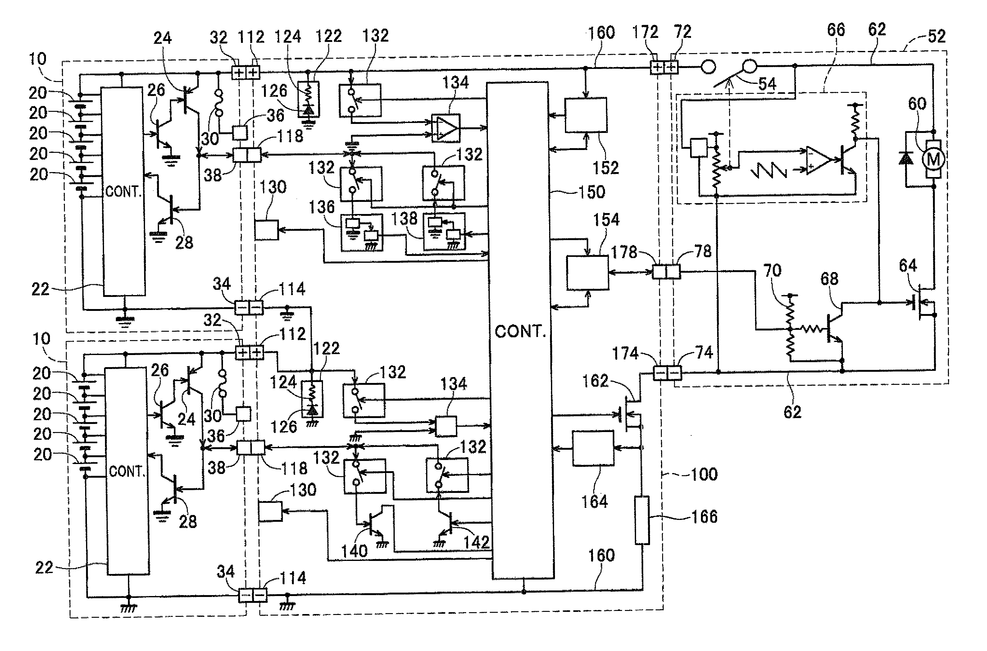
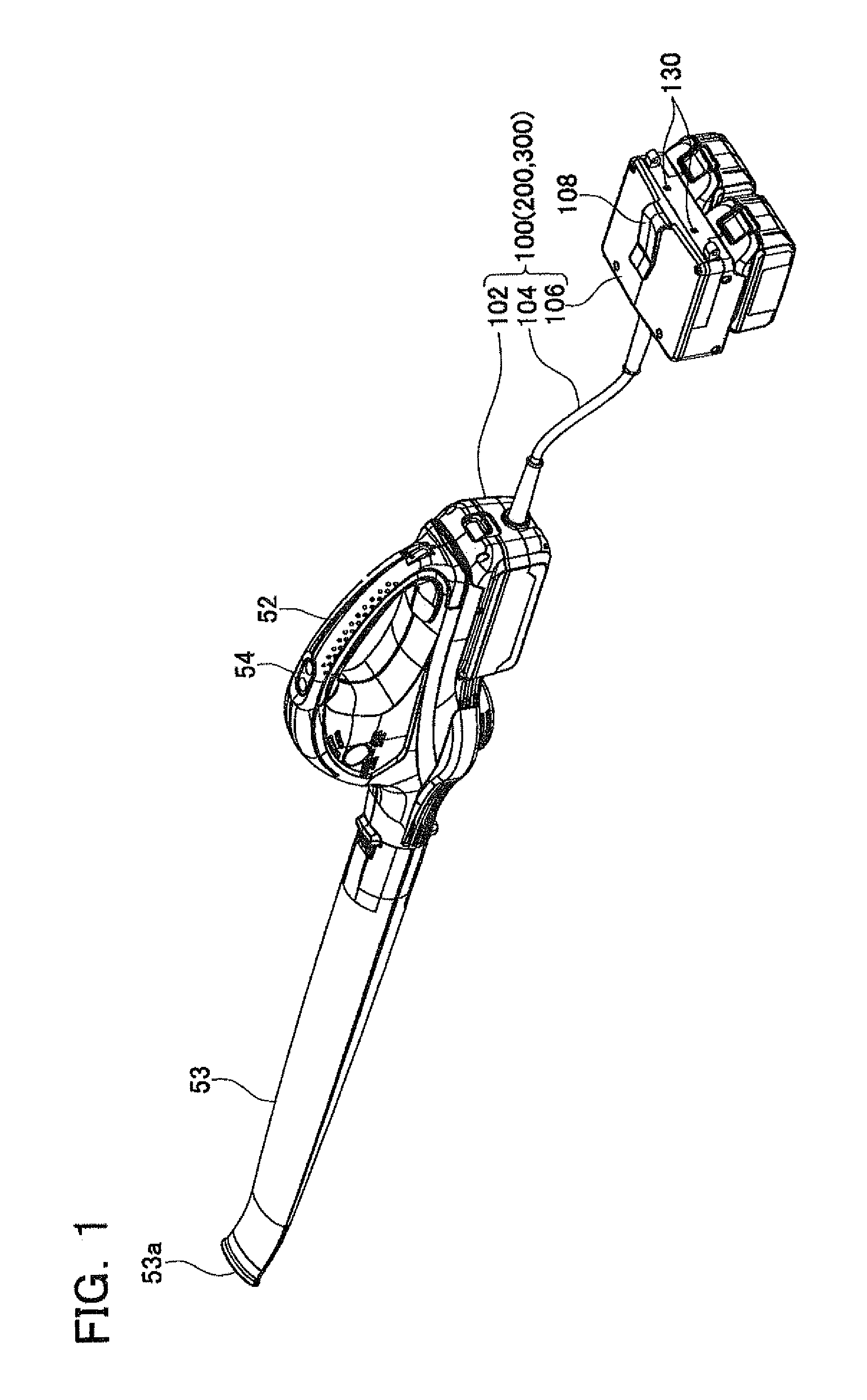
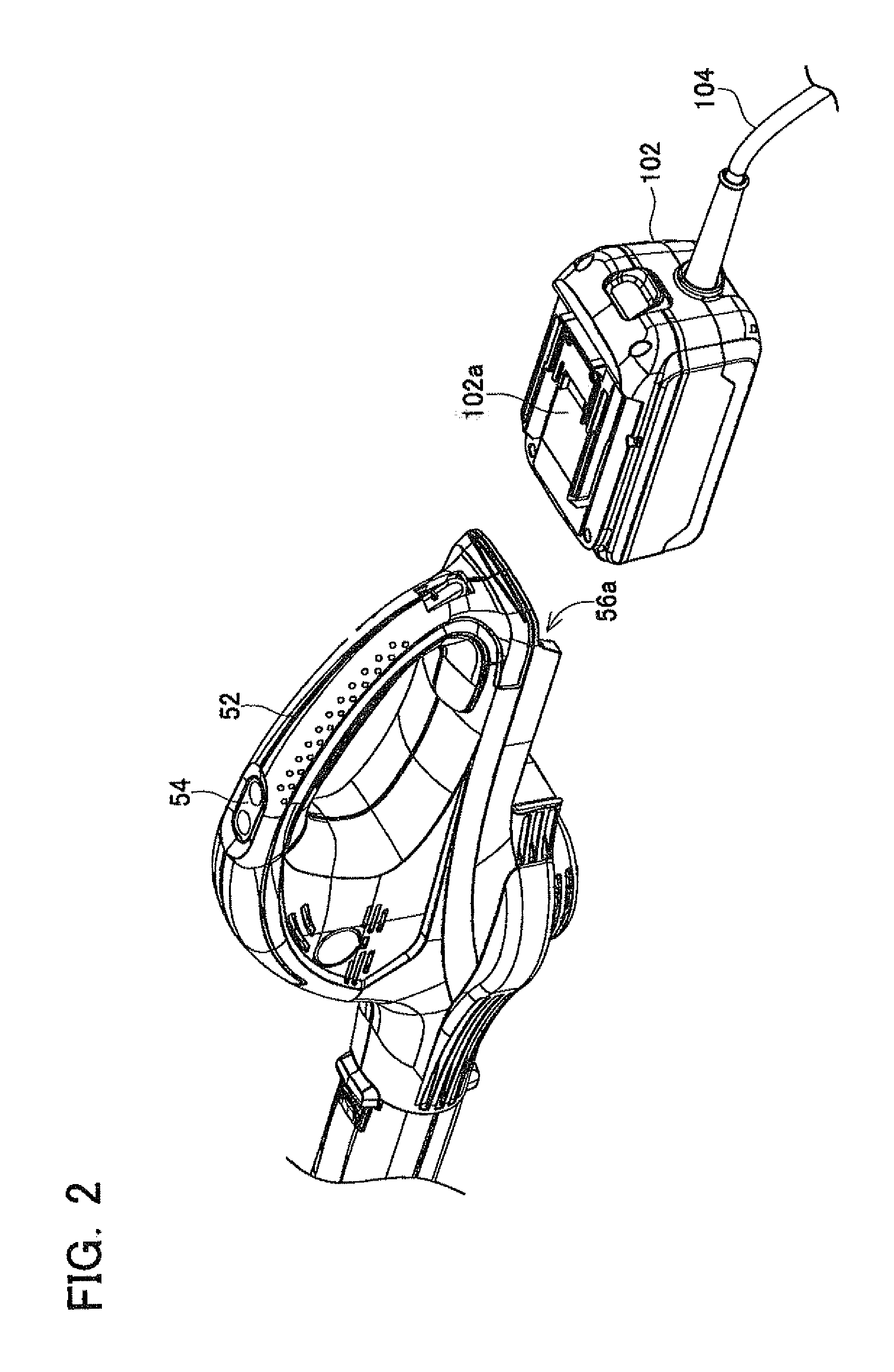
[0040]An adapter 100 according to a first embodiment will be described with reference to the drawings. FIGS. 1, 2, and 3 illustrate an external appearance of the adapter 100. As illustrated in FIGS. 1, 2, and 3, the adapter 100 is a device for electrically connecting two battery packs 10 to a main body 52 of an electric power tool. Here, a rated voltage of the main body 52 of the electric power tool is 36 volts, and a nominal voltage of each battery pack 10 is 18 volts. In general, the main body 52 of the electric power tool uses a battery pack having a nominal voltage of 36 volts and cannot use a battery pack having a nominal voltage of 18 volts. However, according to the adapter 100 of the present embodiment, it is possible to use an electric power tool having a rated voltage of 36 volts using two battery packs 10 having a nominal voltage of 18 volts without requiring a battery pack having a nominal voltage of 36 volts.

[0041]The technique described in this specification can be app...

embodiment 2

[0072]An adapter 200 according to a second embodiment will be described with reference to FIGS. 6, 7, and 8. In the adapter 200 of the second embodiment, two ID terminals 220, two cut-off switches 232, and two level shifters 236 and 238 are added to the configuration of the adapter 100 of the first embodiment. Moreover, a portion of the program of the main controller 150 is modified. Since the other constituent components are the same as those of the first embodiment, these constituent components will be denoted by the same reference numerals as those of the first embodiment, and overlapping description thereof will not be provided.

[0073]One ID terminal 220 is provided in one battery receiving portion 106a, and the other ID terminal 220 is provided in the other battery receiving portion 106a. The ID terminal 220 is electrically connected to the main controller 150. Two cut-off switches 232 and two level shifters 236 and 238 are provided between one ID terminal 220 and the main contr...

embodiment 3

[0080]An adapter 300 according to a third embodiment will be described with reference to FIGS. 9 and 10. In the adapter 300 of the third embodiment, the two battery-side alarm terminals 118 and the cut-off switches 132, the level shifters 136 and 138, and the transistors 140 and 142 connected to the battery-side alarm terminals 118 are removed from the configuration of the adapter 200 of the second embodiment. Moreover, a portion of the program of the main controller 150 is modified. Since the other constituent components are the same as those of the first and second embodiments, these constituent components will be denoted by the same reference numerals as those of the first and second embodiments, and overlapping description thereof will not be provided.

[0081]The adapter 300 of the third embodiment has the ID terminal 220 and can acquire the ID information of the battery packs 14, 16, and 18 similarly to the adapter 200 of the second embodiment. Thus, the adapter 300 can determine...


PUM

PropertyMeasurementUnit
voltageaaaaaaaaaa
voltageaaaaaaaaaa
voltageaaaaaaaaaa

Abstract

An adapter is provided with a connecter portion configured to be detachably attached to the main body of the electric power tool and at least one battery receiving portion configured to be detachably attached to the battery pack. The battery pack attached to the battery receiving portion is electrically coupled with the main body of the power tool attached to the connecter portion via a power supply circuit of the adapter. The adapter is provided with a measuring portion configured to measure an index corresponding to a charged level of the battery pack and a signal receiving portion configured to receive an alarm signal outputted from the battery pack, and is configured to stop or restrict power supply to the main body of the electric power tool based upon a measurement by the measuring portion and the alarm signal that is received.

Description

TECHNICAL FIELD[0001]The present invention relates to an electric power tool powered by a battery pack and an adapter therefor.BACKGROUND ART[0002]U.S. Pat. No. 5,028,858 discloses an electric power tool that is powered by two battery packs. In this electric power tool, two battery packs are connected in series, and a motor is driven with a high voltage. Due to this, the electric power tool can provide higher power that can be used in heavy work than a case where one battery pack is used as a power supply.[0003]When battery packs are connected in series, large load may be applied to one battery pack. For example, if a charged level is different between two battery packs, one battery pack may be overcharged and may be charged in a reverse direction (i.e. reverse-charged) by the other battery pack. In this case, one battery pack may be damaged severely so that deterioration thereof progresses further or the battery pack may become unusable.[0004]With regard to the above problem, in th...

Claims


Application Information

Patent Timeline
Patent Type & Authority Applications(United States)
IPC IPC(8): H02J7/00H02J1/00H01M50/204H01M50/296
CPCH01M2/1022H01M10/0525H02J7/0026H02J7/0031H01M10/48H02J7/0063H01M10/44H01M10/46H02J1/00H01M10/4257H02J7/0014H02J7/0025Y02E60/10H01M50/296H01M50/204H02J7/00
Inventor SUZUKI, HITOSHI
Owner MAKITA CORP
Why Eureka
Try Eureka