Lens module

a technology of lens module and lens body, applied in the field of lens module, can solve the problems of relative uniformity (ru) in the following optical quality tes

Active Publication Date: 2013-03-14
WCUBE
View PDF2 Cites 11 Cited by
  • Summary
  • Abstract
  • Description
  • Claims
  • Application Information

AI Technical Summary

Problems solved by technology

However, because of the manufacturing error, the actual relative illumination curve of the lens module formed under the field of view ranged from 1.1 to 1.2 millimeters is often significantly bent or tapered as shown in section ‘a’ of FIG. 1.
The bent or tapering phenomenon of the relative illumination curve may cause the failure of relative uniformity (RU) in the following optical quality test.

Method used


Image

  • Lens module
  • Lens module
  • Lens module

Examples


Embodiment Construction

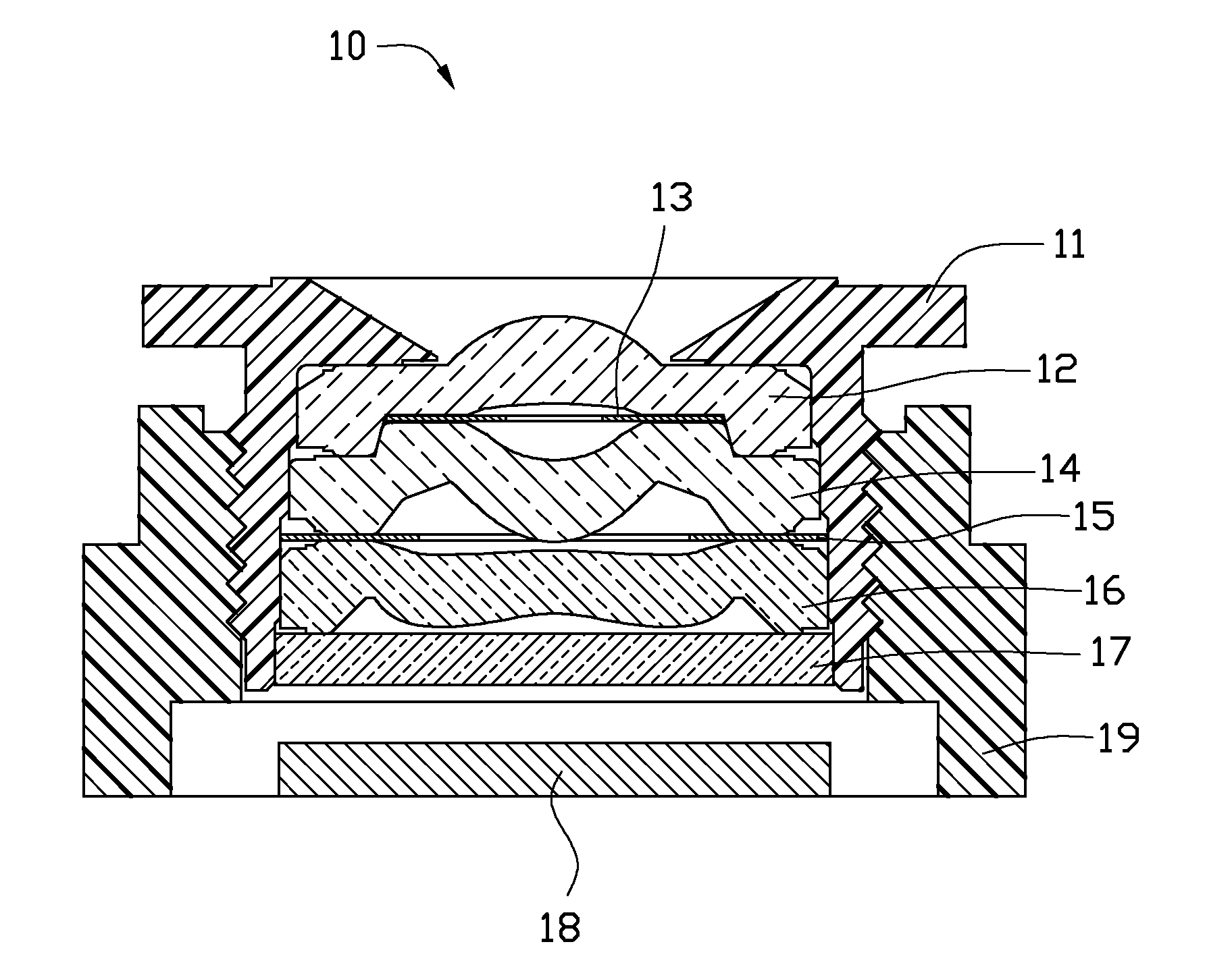
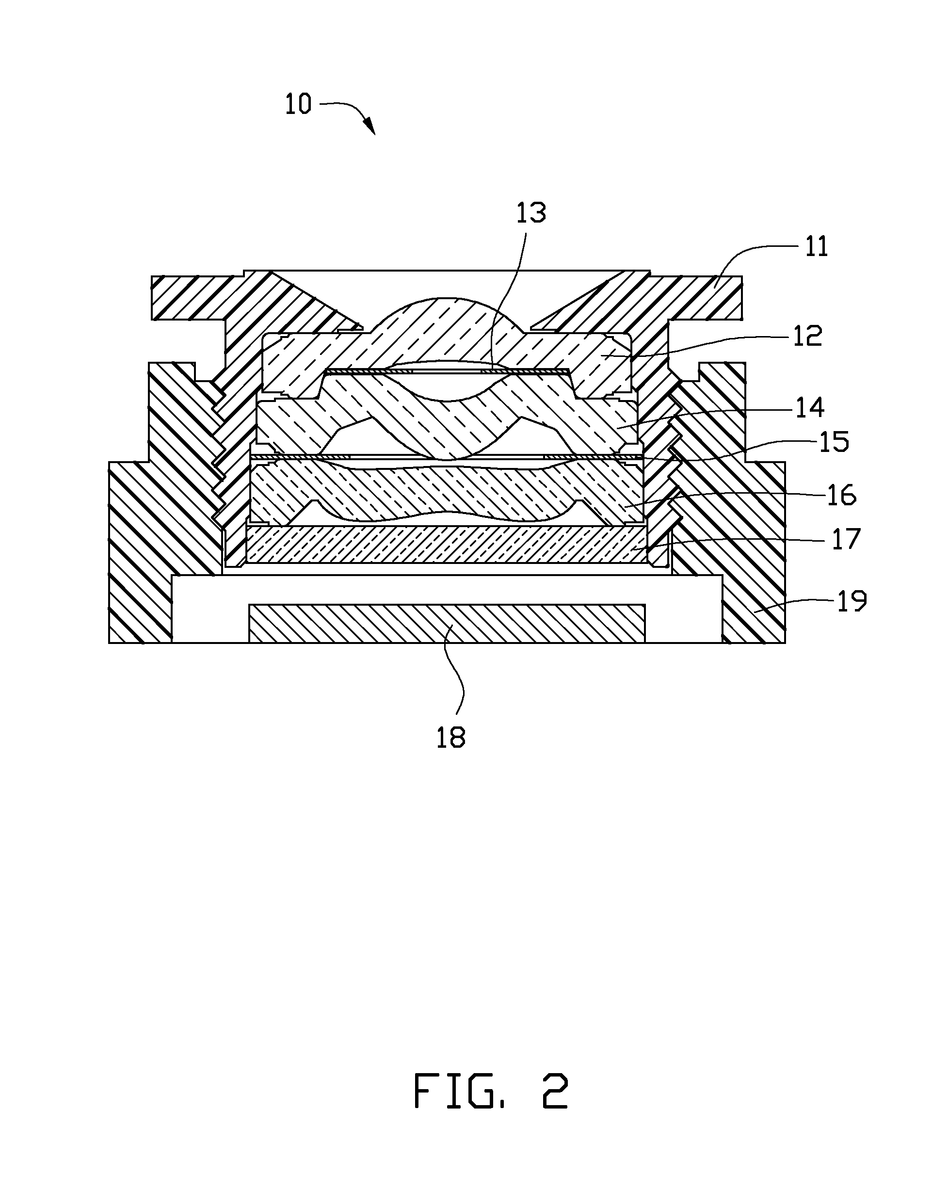
[0010]FIG. 2, is an embodiment of a lens module 10 including a barrel 11, a first lens 12, a first spacer ring 13, a second lens 14, a second spacer ring 15, a third lens 16, an infrared cut-off filter 17, an image sensor 18, and a lens base 19. The barrel 11 is adjustably assembled to the lens base 19 via screw thread engagement. In the illustrated embodiment, one end of the barrel 11 is received into and rotatably engaged with a top end of the lens base 19, such that, the barrel 11 is rotatable relative to the lens base 19 and is capable of being axially adjusted relative to the lens base 19, thereby changing a length of the whole lens module 10.

[0011]The first lens 12, the first spacer ring 13, the second lens 14, the second spacer ring 15, the third lens 16 and the infrared cut-off filter 17 are coaxially assembled within the barrel 11, along an axial direction of the barrel 11 toward the lens base 19 in that order. In this embodiment, the first spacer ring 13 functions as an ap...


PUM


Abstract

A lens module comprises a barrel, a first lens, a first spacer ring, a second lens having an effective aperture A, a second spacer ring having an inner diameter B, and a third lens having an effective aperture C. The first lens, the first spacer ring, the second lens, the second spacer ring, the third lens and the infrared cut-off filter are coaxially assembled within the barrel, along an axial direction of the barrel in that order. The first spacer ring is sandwiched between the first lens and the second lens, the second spacer ring is sandwiched and located between the second lens and the third lens. The inner diameter B of the second spacer ring is smaller than the effective aperture C of the third lens and larger than the effective aperture A of the second lens, so as to satisfy the condition of C>B>A.

Description

BACKGROUND[0001]1. Technical Field[0002]The present disclosure generally relates to a lens module.[0003]2. Description of Related Art[0004]In order to improve the relative illumination (RI) of the lens module, the relative illumination curve of the traditional lens module formed under the field of view ranged from 1.0 to 1.2 millimeters is generally designed to be relatively flat, during the optical design stage. However, because of the manufacturing error, the actual relative illumination curve of the lens module formed under the field of view ranged from 1.1 to 1.2 millimeters is often significantly bent or tapered as shown in section ‘a’ of FIG. 1. The bent or tapering phenomenon of the relative illumination curve may cause the failure of relative uniformity (RU) in the following optical quality test.[0005]Therefore, there is room for improvement within the art.BRIEF DESCRIPTION OF THE DRAWINGS[0006]The components in the drawings are not necessarily drawn to scale, the emphasis i...

Claims


Application Information

Patent Timeline
Patent Type & Authority Applications(United States)
IPC IPC(8): G02B7/04G02B7/02
CPCG02B7/02G02B7/04G02B9/12G02B3/0081G02B3/00G02B7/021G02B13/0035
Inventor LIN, TSUNG-YU
Owner WCUBE
Why Eureka
Try Eureka