Combined frame for an electromechanical box

a technology of electromechanical boxes and combined frames, which is applied in the direction of electrical apparatus casings/cabinets/drawers, dismountable cabinets, packaging foodstuffs, etc., can solve the problems of increasing the cost of transporting the conventional frame, the difficulty of assembly between the beams, the columns and the corner connectors, and the increase of the cost of transporting the conventional combined frame. , to achieve the effect of reducing the cost of transportation and easy assembly and positioning

Inactive Publication Date: 2013-03-21
TAIWAN ENCLOSURE SYST CO LTD
View PDF19 Cites 44 Cited by
  • Summary
  • Abstract
  • Description
  • Claims
  • Application Information

AI Technical Summary

Benefits of technology

[0007]The main objective of the present invention is to provide a combined frame for an electromechanical box that can be assembled and positioned easily, can be assembled without welding and carried conveniently to reduce the cost of transportation.

Problems solved by technology

When the conventional frame is manufactured, the assemblement between the beams, the columns and the corner connectors is difficult and needs to be done in the manufacturing factory.
The large space of the conventional frame will increase the costs for transporting the conventional frame.
However, the beams, the columns and the modular connectors are securely connected to each other by welding after assembling, the fixed structure of the conventional combined frame can not be detached and the large space that the conventional combined frame occupies will increase the costs for transporting the conventional combined frame.

Method used


Image

  • Combined frame for an electromechanical box
  • Combined frame for an electromechanical box
  • Combined frame for an electromechanical box

Examples


Embodiment Construction

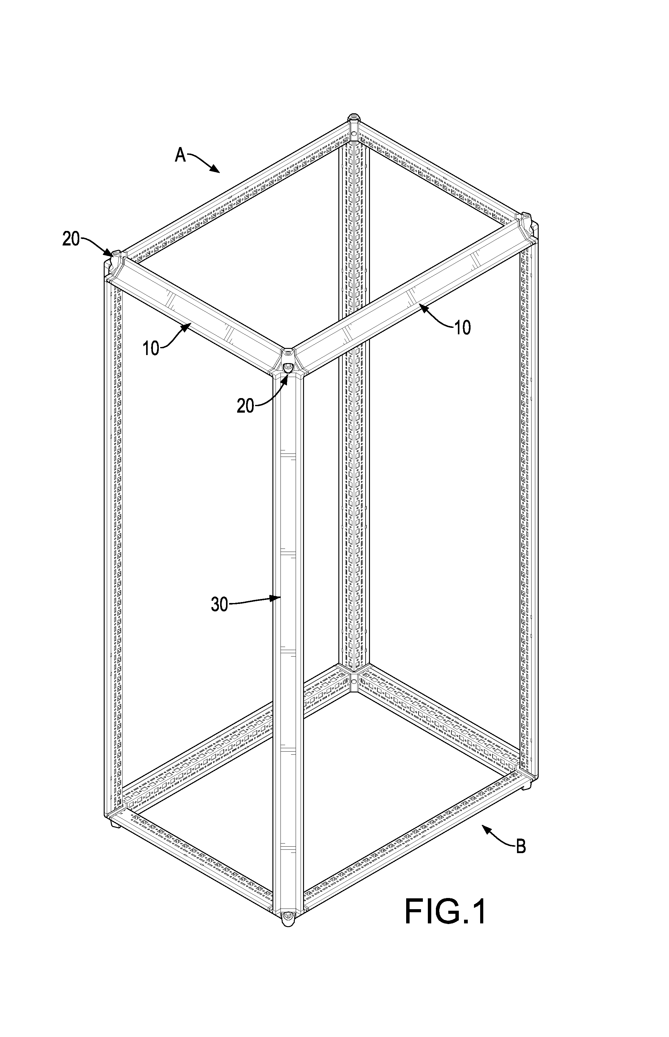
[0025]With reference to FIG. 1, a combined frame in accordance with the present invention for an electromechanical box comprises eight transversal beams 10, eight major connectors 20 and four longitudinal columns 30.

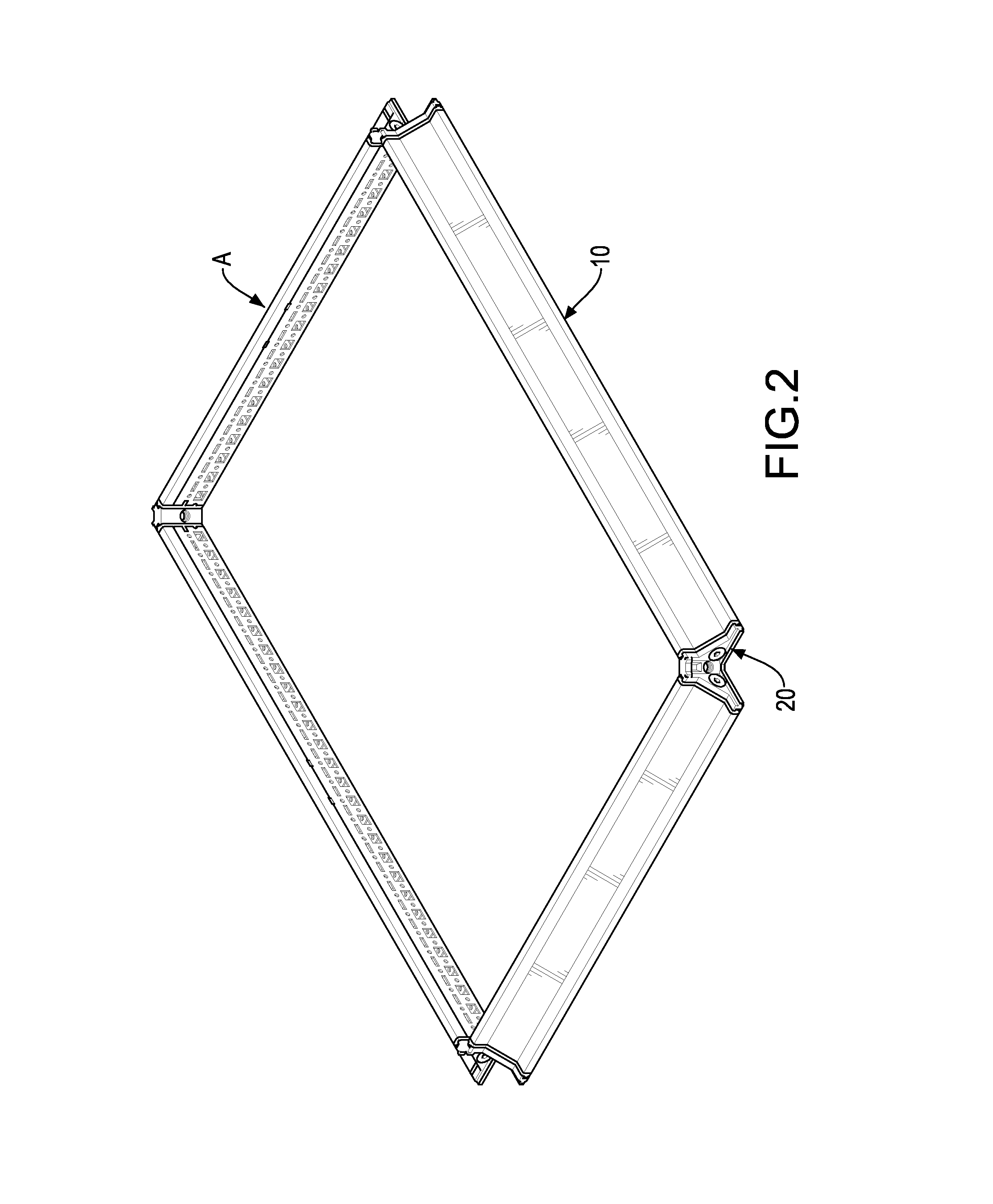
[0026]With reference to FIGS. 2, 3, 4A and 4B, each transversal beam 10 has a body 11, two side covers 12, two waterproof bars 13 and two fasteners 14. The body 11 is L-shaped in cross section and has an external surface, two ends, multiple holding holes and two mounting holes. The holding holes are formed in the external surface of the body 11 at intervals between the ends of the body 11. The mounting holes are respectively formed through the ends of the body 11.

[0027]The side covers 12 are L-shaped, are respectively and securely mounted in the mounting holes of the body 11, and each side cover 12 has an inner side, an outer side, a middle, a positioning bar 120 and a fastening hole 121. The inner side of the side cover 12 abuts a corresponding end of the body 11. The p...


PUM


Abstract

A combined frame for an electromechanical box has eight transversal beams, eight major connectors and four longitudinal columns. Each transversal beam has a body, two side covers and two fasteners. The side covers are securely mounted on the body and each has a fastening hole. The fasteners are respectively connected to the fastening holes of the side covers. Each major connector is connected to two adjacent transversal beams and has an internal surface, an external surface, a bottom, a top, an abutting wall, two through holes and a mounting hole. The longitudinal columns are connected to the major connectors between the transversal beams and each longitudinal column has a body, two minor connectors and two fixing elements. The minor connectors are respectively and securely mounted in the body and are respectively connected to the major connectors.

Description

BACKGROUND OF THE INVENTION[0001]1. Field of the Invention[0002]The present invention relates to a combined frame, and more particularly to a combined frame for an electromechanical box that can be assembled and positioned easily, can be assembled and carried conveniently to reduce the cost of transportation.[0003]2. Description of Related Art[0004]A conventional frame for an electromechanical box is assembled by multiple beams, multiple columns and multiple corner connectors. After assembling the beams, the columns and the corner connectors of the conventional frame, the beams, the columns and the corner connectors are connected to each other by welding. When the conventional frame is manufactured, the assemblement between the beams, the columns and the corner connectors is difficult and needs to be done in the manufacturing factory. The large space of the conventional frame will increase the costs for transporting the conventional frame.[0005]Furthermore, a conventional combined f...

Claims


Application Information

Patent Timeline
Patent Type & Authority Applications(United States)
IPC IPC(8): H05K7/18
CPCH05K7/18F16M1/00H02B1/013H02B1/308A47B47/0008A47F5/01H02B1/014H02B1/01H05K5/0052H05K5/02B65D85/68B65D88/10H05K5/00
Inventor LIU, KENG-FU
Owner TAIWAN ENCLOSURE SYST CO LTD
Why Eureka
Try Eureka