
Method for firing raw ceramic blanks and furnace

a technology of raw ceramics and furnaces, applied in the field of raw ceramic blank firing and furnace, can solve the problems of high design cost of generic furnaces and easy troubl

Inactive Publication Date: 2013-03-21
KELLER HCW
View PDF11 Cites 9 Cited by
  • Summary
  • Abstract
  • Description
  • Claims
  • Application Information

AI Technical Summary

Benefits of technology

The purpose of this invention is to create a method and furnace that are less prone to issues and use less energy overall.

Problems solved by technology

A generic furnace would be expensive to design and would be susceptible to trouble due to the technology used for implementation of the blanks in the firing zone with the goal of reversing the direction.

Method used


Image

  • Method for firing raw ceramic blanks and furnace
  • Method for firing raw ceramic blanks and furnace
  • Method for firing raw ceramic blanks and furnace

Examples


Embodiment Construction

[0036]In the following detailed description numerous specific details are set forth in order to provide a thorough understanding of the invention. However, it will be understood by those skilled in the art that the present invention may be practiced without these specific details. For example, the invention is not limited in scope to the particular type of industry application depicted in the figures. In other instances, well-known methods, procedures, and components have not been described in detail so as not to obscure the present invention.

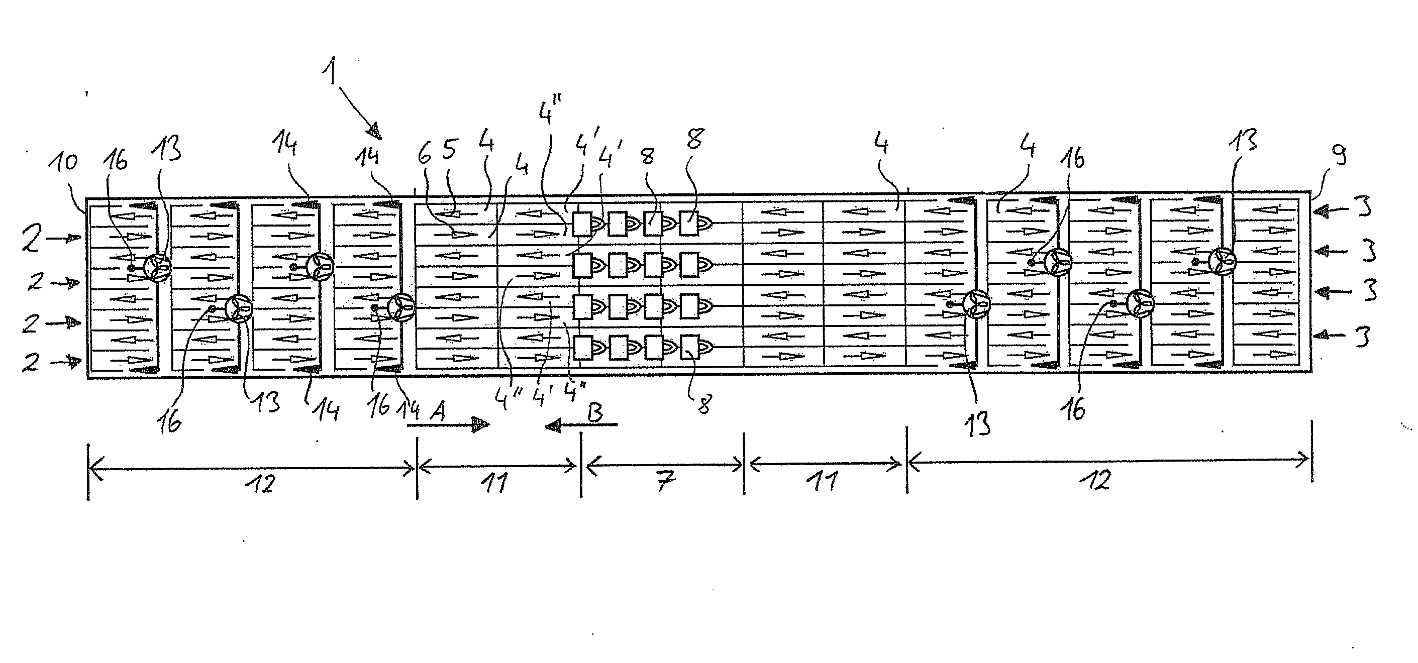
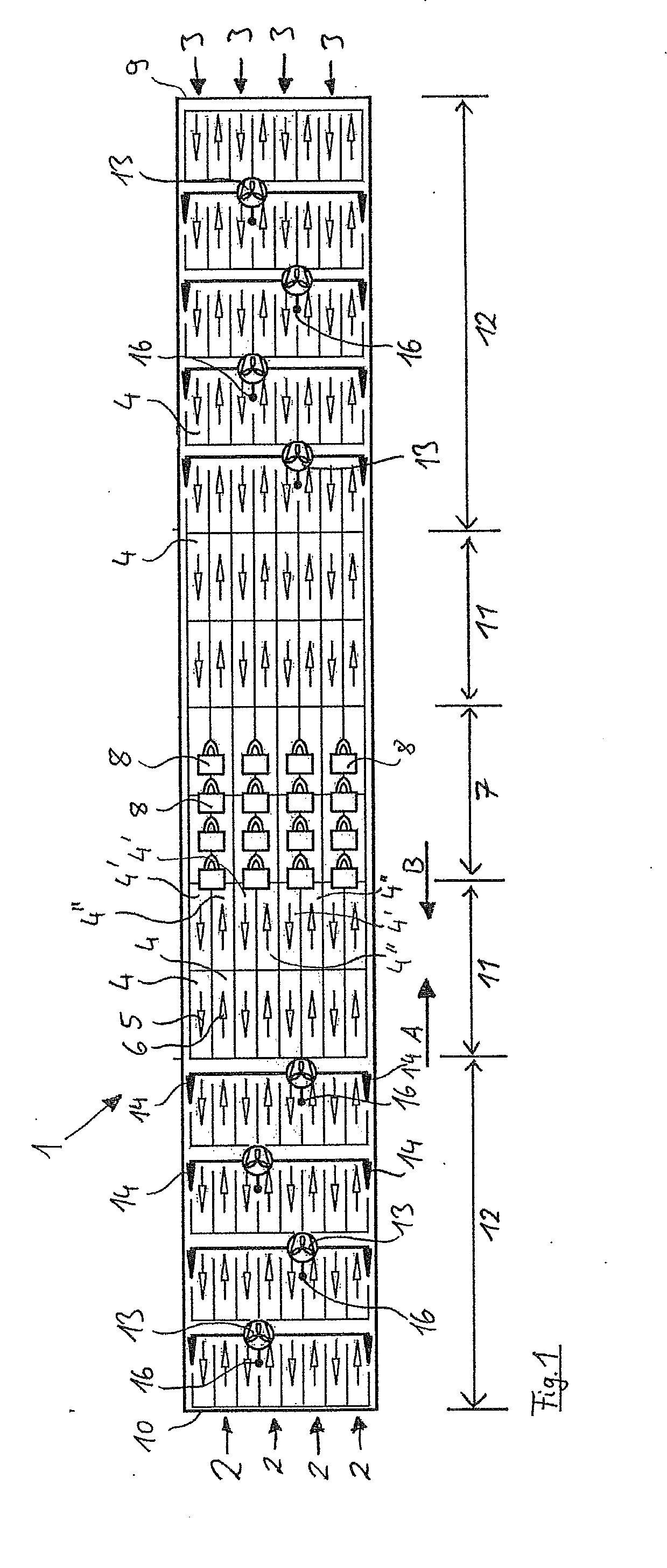
[0037]FIG. 1 shows a schematic and partially perspective top view of an object according to the invention. This shows a furnace section, which is labeled in general as numeral 1, and on which a total of eight furnace trains are arranged. In the plane of the figure, furnace trains labeled with the numeral 2 travel in the direction A, i.e., to the right, while furnace trains labeled with the numeral 3 travel in the direction B, i.e., to the left....


PUM

PropertyMeasurementUnit
Temperatureaaaaaaaaaa
Ratioaaaaaaaaaa

Abstract

A method for firing raw ceramic blanks in a furnace includes the steps of guiding trains of blanks running parallel to one another along a longitudinal furnace section having a firing zone, wherein the trains are moved in opposite directions during one movement operation, and the furnace is loaded using blanks to be moved in a first direction. A furnace for firing raw ceramic blanks having a plurality of trains which are arranged parallel to one another and can move along a longitudinal furnace section, so trains comprising a plurality of furnace bogies on which the blanks are to be arranged, wherein the furnace section has a firing zone, and wherein the trains are moved in opposite directions, and the furnace is at a first end of the furnace section for loading the blanks to be moved in a first direction into the furnace.

Description

CROSS REFERENCE[0001]This application claims priority to German Patent Application No. 10 2011 112 838.0, filed Sep. 12, 2011.BACKGROUND OF THE INVENTION[0002]DE 44 42 850 A1 describes related art. A generic furnace would be expensive to design and would be susceptible to trouble due to the technology used for implementation of the blanks in the firing zone with the goal of reversing the direction. The same thing is also true of the cooling air supply that is used.SUMMARY OF THE INVENTION[0003]The object of the present invention is to design a method and / or a furnace of the type identified previously, so that it will be less susceptible to trouble and will be energy saving on the whole.[0004]The object defined above is achieved by a method according to the invention as defined in claim 1 and by an object according to the invention as defined in claim 11.[0005]The method according to the invention is characterized in that the blanks to be moved in the opposite second direction B are ...

Claims


Application Information

Patent Timeline
IPC IPC(8): F27B9/02F27D15/00F27B9/10
CPCF27B9/022F27B9/10F27D15/00F27B17/0041F27B9/3011F27B9/38F27B9/39F27B9/3005Y02P40/60C04B33/32F27B9/20F27B2009/3615F27B2009/3016
Inventor GAUSMANN, HEINERHEITMANN, PETERHUSING, RAINER
Owner KELLER HCW
Learn More