Embolic Coil Delivery System

a delivery system and embolism technology, applied in the direction of dilators, occulders, surgery, etc., can solve problems such as drawbacks in the delivery procedur

Active Publication Date: 2013-03-21
COOK MEDICAL TECH LLC
View PDF6 Cites 7 Cited by
  • Summary
  • Abstract
  • Description
  • Claims
  • Application Information

AI Technical Summary

Problems solved by technology

Unfortunately, this delivery procedure suffers drawbacks, including those caused by the resistance created by the one or more coils loaded into the catheter lumen.
For example, this resist

Method used


Image

  • Embolic Coil Delivery System
  • Embolic Coil Delivery System
  • Embolic Coil Delivery System

Examples


Embodiment Construction

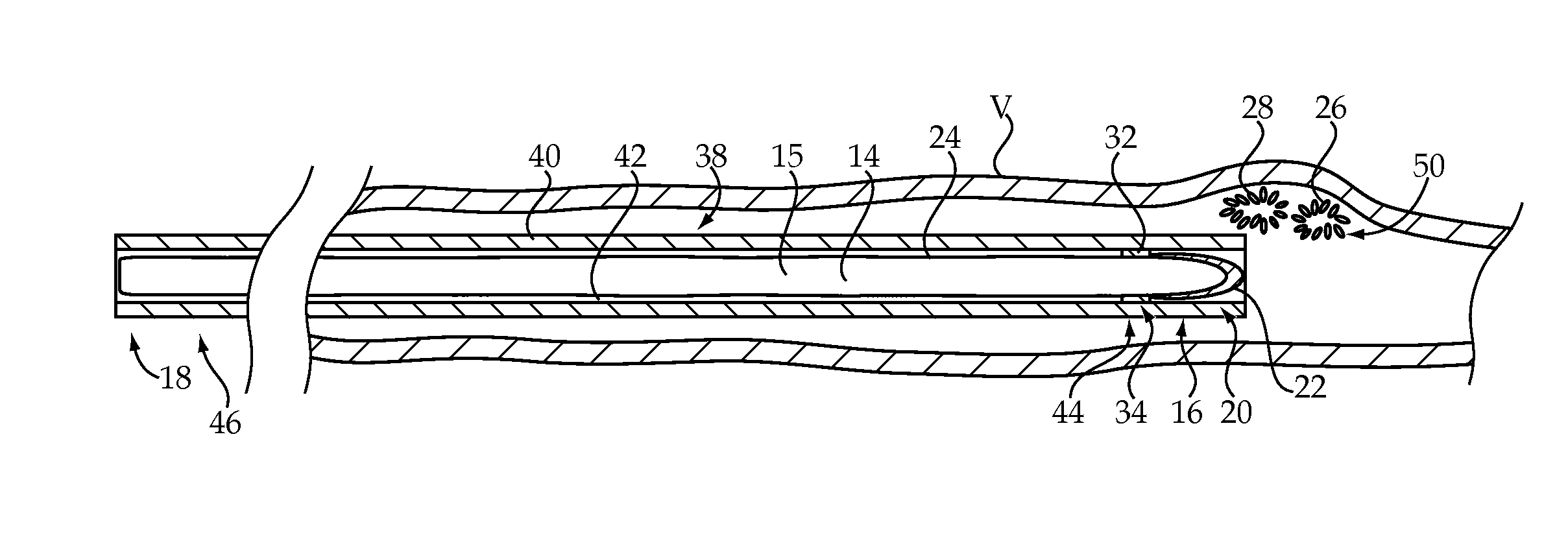
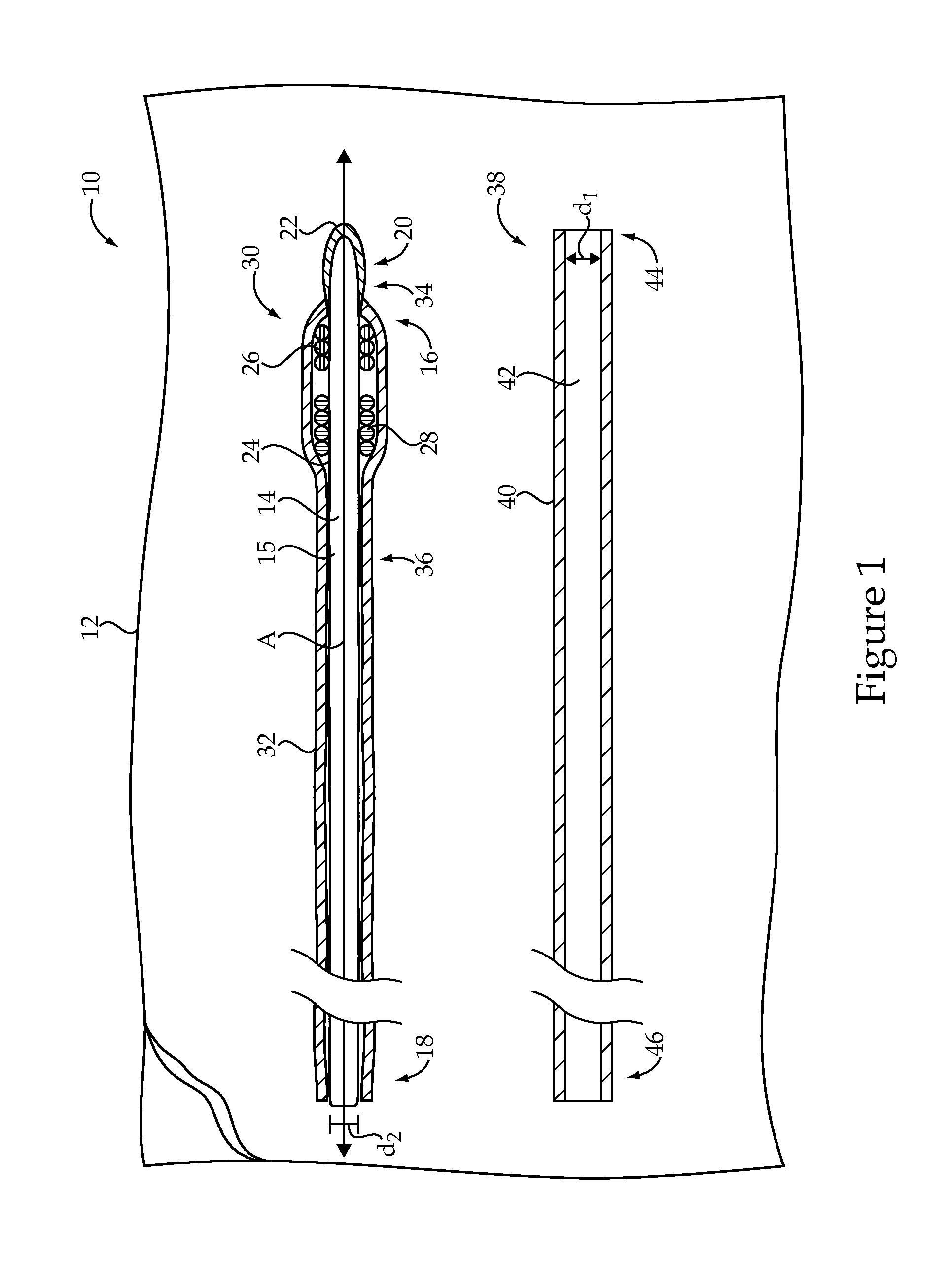
[0014]Referring to FIG. 1, there is shown an embolic coil delivery system 10 according to one embodiment of the present disclosure. The embolic coil delivery system 10 may include a number of components, which may be provided within a sterile, tear open package 12, as is known in the art. In performing an embolic coil delivery procedure on a patient, some or all of the components of the embolic coil delivery system 10 may be used, depending upon the specifics of the procedure to be performed. As should be appreciated, however, the components shown in FIG. 1 might be separately packaged and / or the embolic coil delivery system 10 might also include components in addition to those shown, including components routinely used in percutaneous endovascular procedures.

[0015]The embolic coil delivery system 10 may generally include a flexible elongate body 14, which may be a solid structure, as shown, or may be hollow, with an outer tube defining an internal lumen. According to the exemplary ...


PUM


Abstract

An embolic coil delivery system includes a flexible elongate body having a distal segment. An embolic coil is loaded on the flexible elongate body at the distal segment and contacts an outer surface of the flexible elongate body. The embolic coil delivery system also includes a delivery catheter sized to advance over the flexible elongate body during an embolic coil delivery procedure, wherein a distal segment of the delivery catheter contacts the embolic coil during the embolic coil delivery procedure.

Description

RELATION TO OTHER PATENT APPLICATION[0001]This application claims priority to provisional patent application 61 / 535,553, filed Sep. 16, 2011, with the same title.TECHNICAL FIELD[0002]The present disclosure relates generally to an embolic coil delivery system, and more particularly to a system for loading an embolic coil on an outer surface of a flexible elongate body and advancing a delivery catheter over the flexible elongate body to contact and unload the embolic coil.BACKGROUND[0003]Embolization procedures are designed to create an artificial blockage within a vessel to block blood from flowing downstream from the blockage. These procedures are used to treat several conditions, including, for example, aneurysms, hemorrhages, and lesions or growths. Specifically, for example, an embolic device may be used to occlude blood flow to an aneurysm and, thus, reduce the risk of the aneurysm rupturing and producing internal hemorrhaging. Embolic devices may include physical barriers, such...

Claims


Application Information

Patent Timeline
IPC IPC(8): A61M29/00
CPCA61B17/1214A61B17/12113A61B2017/1205
Inventor CAGE, LOGAN MICHAELREEVES, SARAH ELIZABETH
Owner COOK MEDICAL TECH LLC
Why Eureka
Try Eureka