Method for operating a vapour compression system using a subcooling value

a vapour compression and subcooling value technology, applied in the direction of compression machines with non-reversible cycles, climate sustainability, light and heating apparatus, etc., can solve the problems of damage to the compressor, liquid refrigerant may reach the compressor, and the evaporating capacity of the evaporator is not fully used, so as to achieve the effect of stable operation of the vapour compression system

Active Publication Date: 2013-03-28
DANFOSS AS
View PDF12 Cites 26 Cited by
  • Summary
  • Abstract
  • Description
  • Claims
  • Application Information

AI Technical Summary

Benefits of technology

[0008]It is an even further object of embodiments of the invention to provide a vapour compression system in which the potential refrigeration capacity of an evaporator can be utilised to the greatest possible extent, without introducing instabilities in the operation of the vapour compression system.
[0043]The internal heat exchanger may be a parallel flow heat exchanger, i.e. the refrigerant flowing in the internal heat exchanger from the condenser towards the expansion device and the refrigerant flowing in the internal heat exchanger from the evaporator towards the compressor may flow in parallel. As described above, the coldest refrigerant entering the internal heat exchanger from the evaporator is thereby brought into thermal contact with the hottest refrigerant entering the internal heat exchanger from the condenser. This has the consequence that the operation of the vapour compression system becomes relatively stable.

Problems solved by technology

However, in the case that liquid refrigerant is allowed to pass through the evaporator there is a risk that this liquid refrigerant may reach the compressor.
This may cause damage to the compressor and is therefore undesirable.
One disadvantage of the control strategy described above is, that the evaporating capacity of the evaporator is not utilised fully, because the superheat of the refrigerant leaving the evaporator must be positive in order to ensure that liquid refrigerant does not reach the compressor.

Method used


Image

  • Method for operating a vapour compression system using a subcooling value
  • Method for operating a vapour compression system using a subcooling value
  • Method for operating a vapour compression system using a subcooling value

Examples


Embodiment Construction

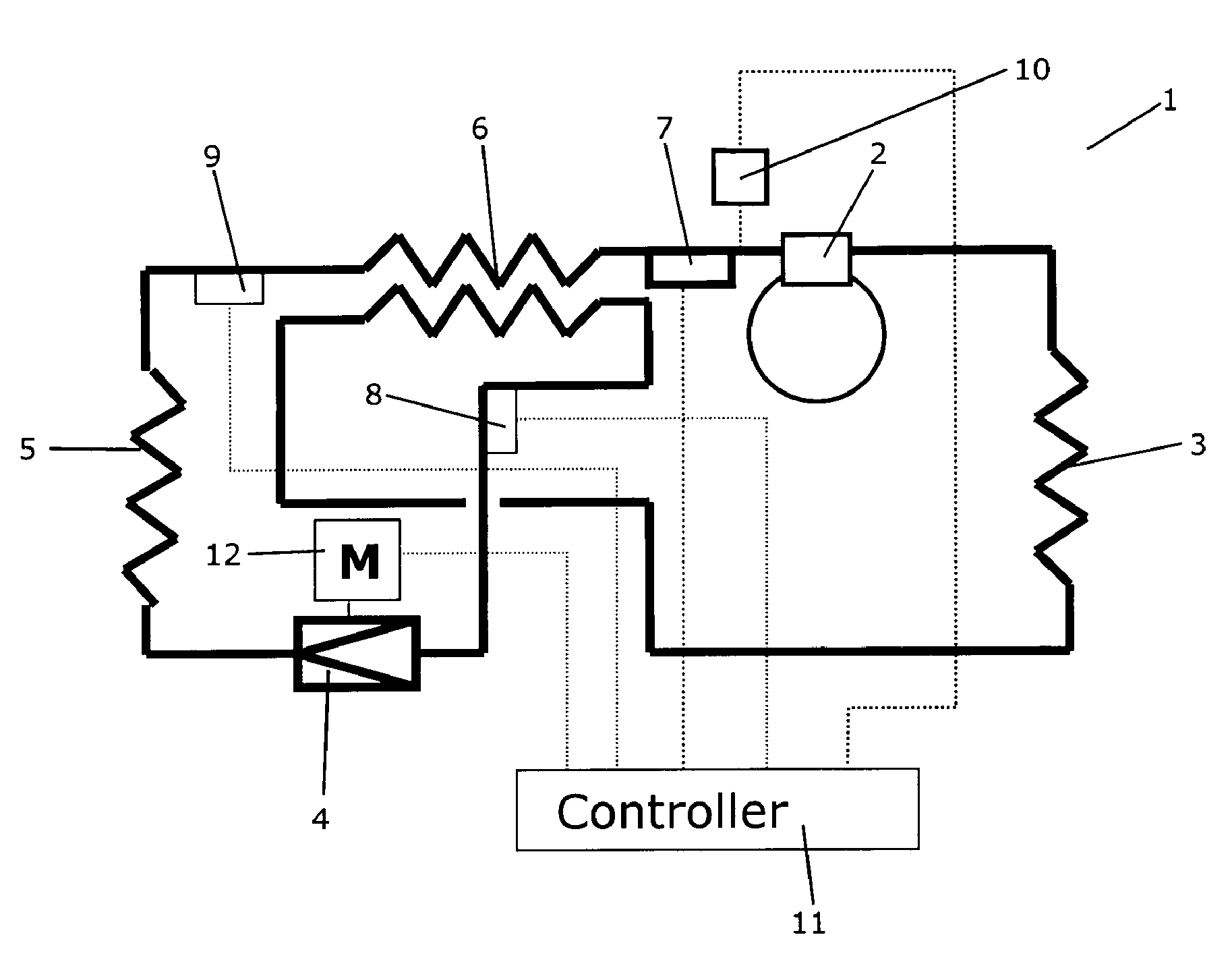
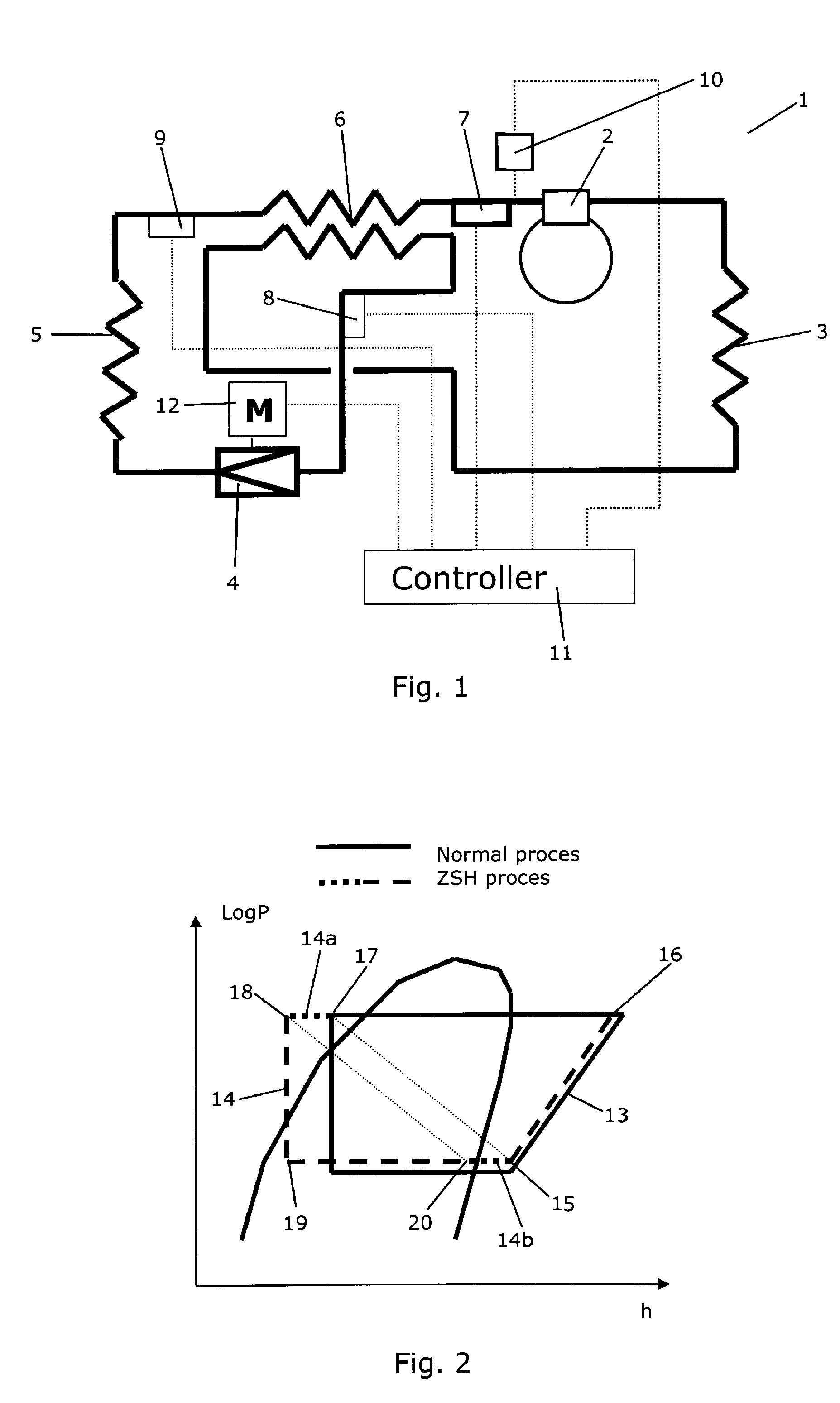
[0049]FIG. 1 is a diagrammatic view of a vapour compression system 1 according to an embodiment of the invention. The vapour compression system 1 comprises a compressor 2, a condenser 3, an expansion device 4 in the form of an expansion valve, and an evaporator 5. The vapour compression system 1 further comprises an internal heat exchanger 6 arranged in the suction line of the vapour compression system 1. In the internal heat exchanger 6 heat exchange takes place between refrigerant flowing in the suction line from the evaporator 5 towards the compressor 2, and refrigerant flowing from the condenser 3 towards the expansion device 4. Thereby cool refrigerant flowing from the evaporator 5 towards the compressor 2 is heated, while hot refrigerant flowing from the condenser 3 towards the expansion device 4 is cooled. The internal heat exchanger 6 is a parallel flow heat exchanger, i.e. the two flows of refrigerant flow in parallel in the internal heat exchanger 6.

[0050]As described abov...


PUM


Abstract

A vapour compression system comprises a compressor, a condenser, an expansion device, e.g. in the form of an expansions valve, and an evaporator arranged along a refrigerant path. A method for operating the vapour compression system comprises the steps of: obtaining a superheat value being representative for the superheat of refrigerant entering the compressor; obtaining a subcooling value being representative for the subcooling of refrigerant entering the expansion device; and operating the expansion device on the basis of the obtained superheat value and on the basis of the obtained subcooling value. The subcooling value is taken into account when operating the expansion device, because variations in the subcooling value have significant influence on the refrigerating capacity of the evaporator at a given opening degree of the expansion device, thereby resulting in a more stable operation of the system. The system may further comprise an internal heat exchanger.

Description

CROSS REFERENCE TO RELATED APPLICATIONS[0001]This application is entitled to the benefit of and incorporates by reference essential subject matter disclosed in International Patent Application No. PCT / DK2011 / 000076 filed on Jun. 29, 2011 and Danish Patent Application No. PA 2010 00577 filed Jun. 30, 2010.FIELD OF THE INVENTION[0002]The present invention relates to a method for operating a vapour compression system, in particular a vapour compression system comprising a suction line heat exchanger. The method of the invention allows the vapour compression system, in particular vapour compression systems comprising a suction line heat exchanger, to be operated in a more stable manner than prior art methods. The invention further relates to a vapour compression system comprising a suction line heat exchanger.BACKGROUND OF THE INVENTION[0003]A vapour compression system usually comprises a compressor, a condenser, an expansion device and an evaporator arranged along a refrigerant path. R...

Claims


Application Information

Patent Timeline
Patent Type & Authority Applications(United States)
IPC IPC(8): F25B49/02
CPCF25B40/00F25B41/062F25B49/02F25B2600/19F25B2700/21175F25B2600/2513F25B2700/2103F25B2700/21151F25B2600/21F25B41/34Y02B30/70
Inventor SCHMIDT, FREDE
Owner DANFOSS AS
Why Eureka
Try Eureka