Pneumatic Tire

a pneumatic tire and tire body technology, applied in the field of pneumatic tires, can solve the problems of difficult to reduce air resistance and suppress temperature increases, more prone to temperature increases, and more prone to air resistance on the outer side of the vehicle, so as to reduce air resistance and reduce temperature. increase, the effect of reducing the difficulty of temperature increas

Inactive Publication Date: 2013-03-28
YOKOHAMA RUBBER CO LTD
View PDF12 Cites 1 Cited by
  • Summary
  • Abstract
  • Description
  • Claims
  • Application Information

AI Technical Summary

Benefits of technology

[0016]According to the pneumatic tire of the present technology, the inner side disposal region in which the inner side recesses are provided and the outer side disposal region in which the outer side recesses are provided may be different regions in a plane projected in a tire width direction. Therefore, the inner side disposal region is configured to have an arrangement suitable for the tire side portion on the inner side in the width direction of the vehicle and, thereby, the ease of temperature increase in the tire side portion on the vehicle inner side can be taken into consideration. Moreover, the outer side disposal region is configured to have an arrangement suitable for the tire side portion on the outer side in the width direction of the vehicle and, thereby, the ease of separation of air of the tire side portion on the vehicle outer side can be taken into consideration. As a result, the arrangements of the inner side disposal region and the outer side disposal region are optimized and, thereby, the air resistance can be reduced and the temperature increases can be suppressed.

Problems solved by technology

Therefore, the side wall portion on the vehicle outer side is more prone to be affected by air resistance compared with the side wall portion on the vehicle inner side.
On the other hand, the side wall portion on the vehicle inner side is housed in the wheel housing of the vehicle and, therefore, is more prone to temperature increases compared with the side wall portion of the vehicle outer side, which is exposed.
Therefore, it is difficult to reduce the air resistance and suppress the temperature increases.
Likewise, in cases where the plurality of recesses is provided only in the outer side in the width direction of the vehicle, the plurality of recesses is not provided in the inner side in the width direction of the vehicle and, as a result, it is difficult to suppress the temperature increases of the side wall portion on the vehicle inner side.

Method used


Image

  • Pneumatic Tire
  • Pneumatic Tire
  • Pneumatic Tire

Examples


embodiment

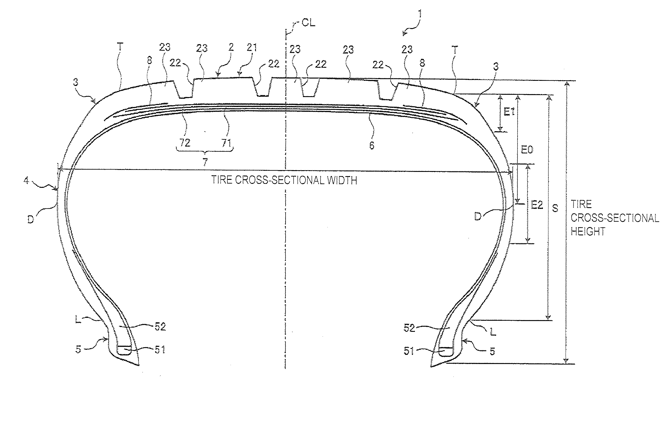
[0024]FIG. 1 is a meridian cross-sectional view of a pneumatic tire according to this embodiment. In the following description, “tire radial direction” refers to a direction orthogonal to the rotational axis (not shown) of the pneumatic tire 1; “inner side in the tire radial direction” refers to the side facing the rotational axis in the tire radial direction; and “outer side in the tire radial direction” refers to the side distanced from the rotational axis in the tire radial direction. “Tire circumferential direction” refers to a circumferential direction with the rotational axis as a center axis. Additionally, “tire width direction” refers to the direction parallel to the rotational axis; “inner side in the tire width direction” refers to the side facing a tire equatorial plane CL (tire equator line) in the tire width direction; and “outer side in the tire width direction” refers to the side distanced from the tire equatorial plane CL in the tire width direction. “Tire equatorial...

examples

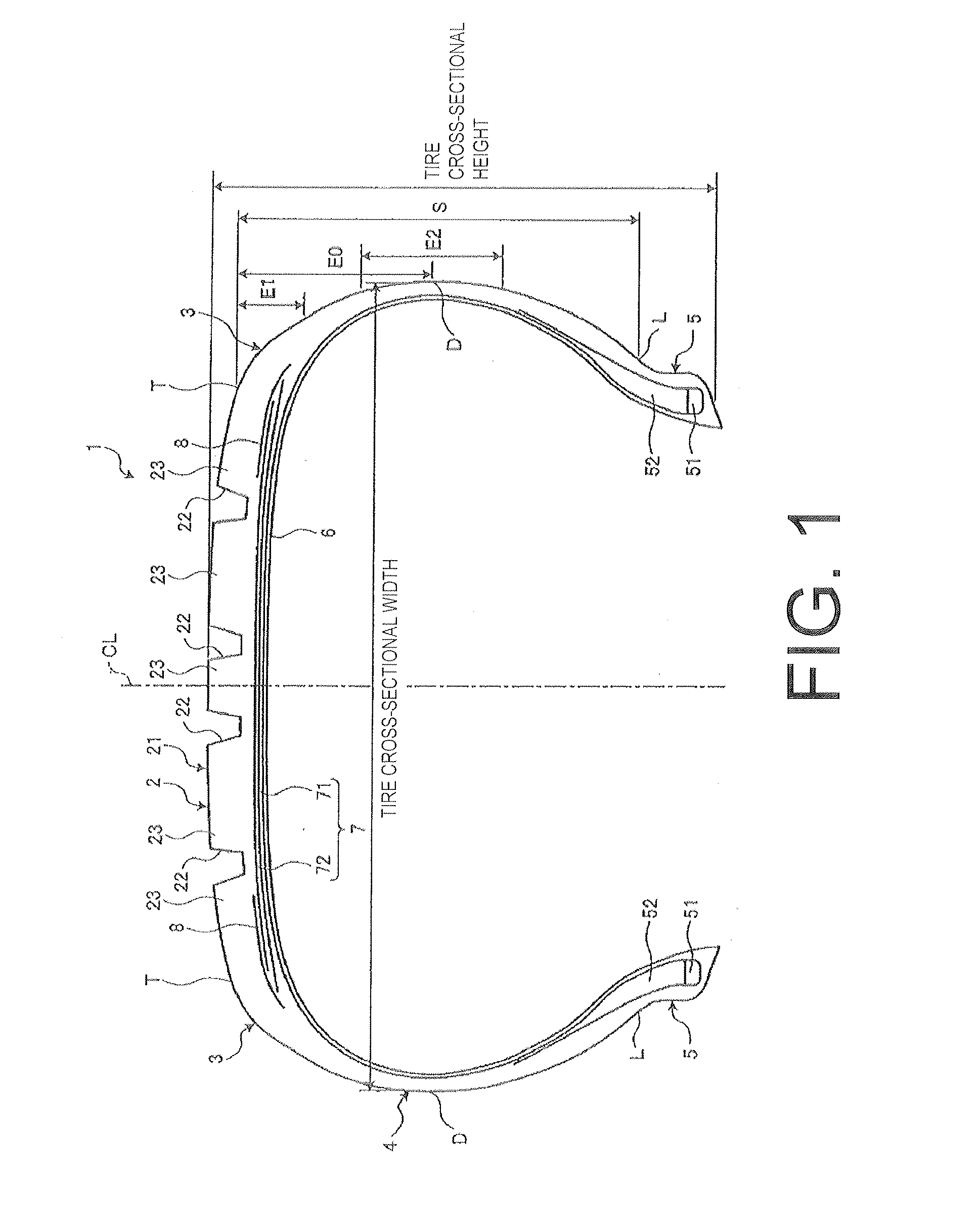
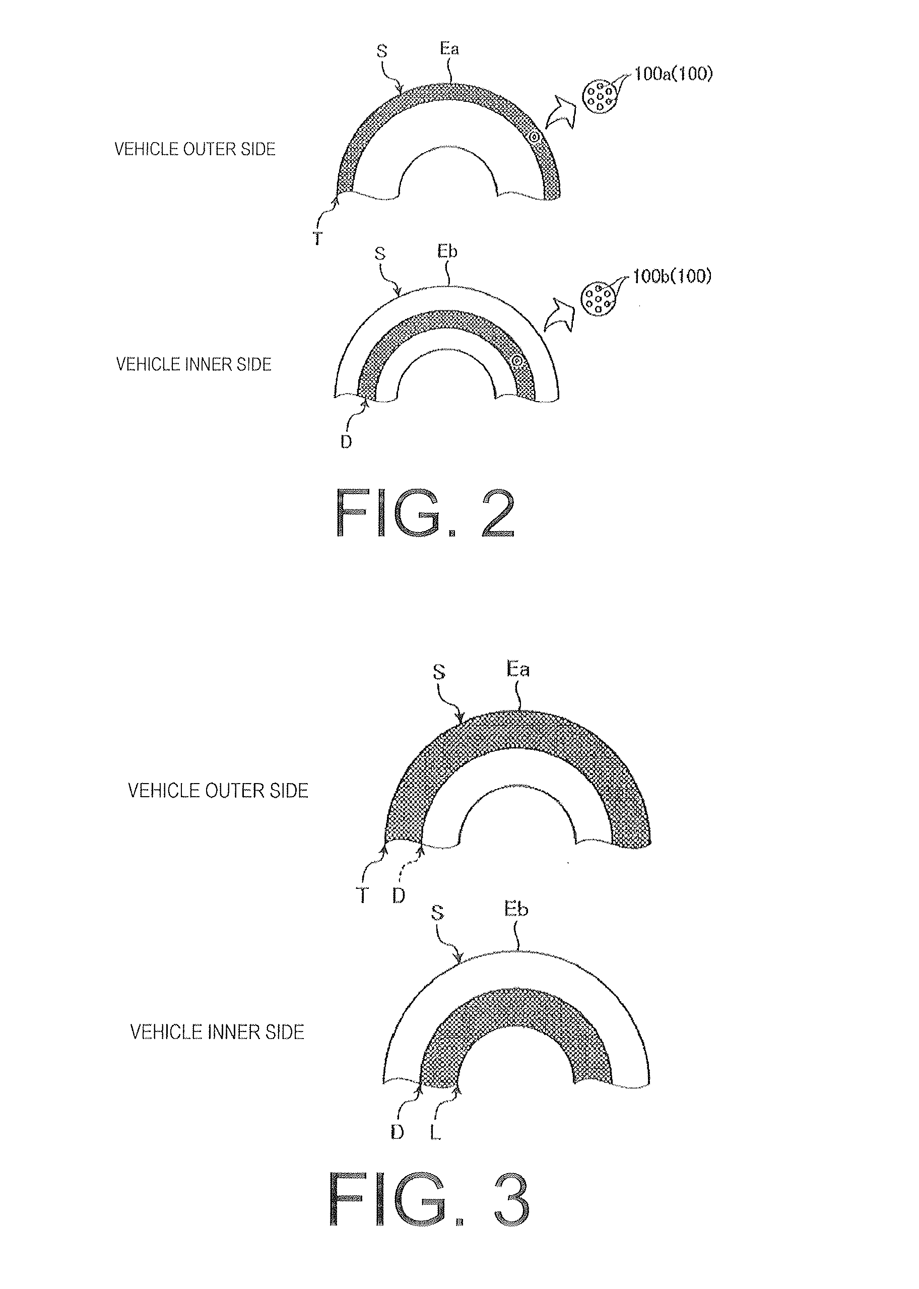
[0056]Next, Working Examples 1 to 4, in which the embodiment is applied, are described while referencing FIG. 6, and the temperature increase suppressing performance and air resistance reducing performance of the tire side portion S of each of Working Examples 1 to 4 are compared. Note that the Conventional Example, which is given for the purpose of comparison, is a pneumatic tire in which the outer side recesses 100a and the inner side recesses 100b are not provided in the tire side portion S of the vehicle outer side and the vehicle inner side. Here, the temperature increase suppressing performance and the air resistance reducing performance of the Conventional Example and of Working Examples 1 to 4 were evaluated under the following evaluation conditions.

[0057]As evaluation conditions, a pneumatic tire 1 having a size of 1.85 / 65R15 was used and this pneumatic tire 1 was mounted on a compact front-wheel drive car having an engine displacement of 1,300 cc. Then, the compact front-w...


PUM


Abstract

A pneumatic tire having tire side portions S on both sides that form regions from a ground contact edge to a rim check line includes a plurality of inner side recesses provided in a surface of the tire side portion on a vehicle inner side, when mounted on a vehicle; and a plurality of outer side recesses provided in a surface of the tire side portion on a vehicle outer side, when mounted on a vehicle. In this pneumatic tire, a region where the plurality of inner side recesses is provided is an inner side disposal region and a region where the plurality of outer side recesses is provided is an outer side disposal region. The inner side disposal region and the outer side disposal region are different regions in a plane projected in a tire width direction.

Description

PRIORITY CLAIM[0001]Priority is claimed to Japan Patent Application Serial No. 2011-212788 filed on Sep. 28, 2011.BACKGROUND[0002]1. Technical Field[0003]The present technology relates to a pneumatic tire.[0004]2. Related Art[0005]A pneumatic tire provided with a circular decorative body in at least one side wall portion is known (e.g. see Japanese Unexamined Patent Application Publication No. H11-321243A). In such a pneumatic tire, a plurality of protrusions is formed on a surface of the circular decorative body. By forming the plurality of protrusions, unevennesses occurring in the side wall portion and appearance flaws of the tire caused by mold processing can be obscured.[0006]Additionally, a pneumatic tire provided with a plurality of recesses in a tire outer side surface, throughout a tire circumferential direction and a tire radial direction, is known (e.g. see Japanese Unexamined Patent Application Publication No. 2010-260377A). In such a pneumatic tire, air resistance when ...

Claims


Application Information

Patent Timeline
Patent Type & Authority Applications(United States)
IPC IPC(8): B60C13/02
CPCB60C3/06B60C13/02
Inventor MIYAJIMA, HIROYUKIKUWAJIMA, MASATOSHI
Owner YOKOHAMA RUBBER CO LTD
Why Eureka
Try Eureka