
Optical fiber instrument system and method with motion-based adjustment

a technology of optical fiber and instrument system, applied in the field of robot controlled systems, can solve the problems of limited control and manipulation ability of system components such as catheters and associated working instruments, and surgeons are not able to see directly into patients, so as to prevent the fiber from twisting

Active Publication Date: 2013-04-04
KONINKLIJKE PHILIPS ELECTRONICS NV
View PDF2 Cites 46 Cited by
  • Summary
  • Abstract
  • Description
  • Claims
  • Application Information

AI Technical Summary

Benefits of technology

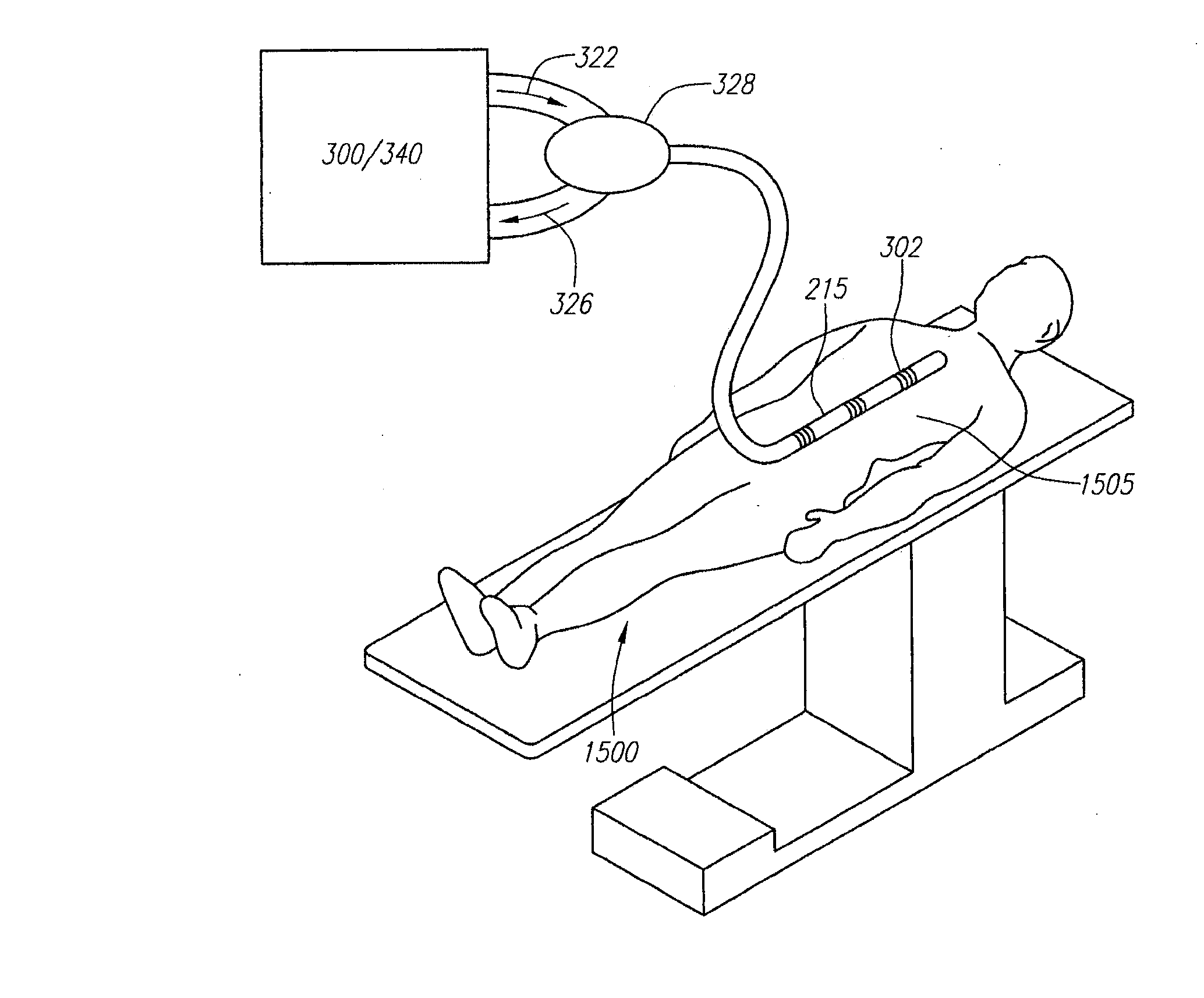
The patent describes a system that uses optical fibers to monitor a patient's respiration. The optical fibers are attached to the patient's body or a stabilization structure, and the system analyzes signals from the fibers to determine the patient's position and orientation. This information can be used to assess the patient's respiration. The patent presents multiple embodiments and demonstrates the potential use of this technology in medical applications.

Problems solved by technology

Without a traditional large and invasive incision, the surgeon is not able to see directly into the patient.
MIS procedures may involve minor surgery as well as more complex operations.
In known robotic instrument systems, however, the ability to control and manipulate system components such as catheters and associated working instruments may be limited due, in part, to a surgeon not having direct access to the target site and not being able to directly handle or control the working instrument at the target site.

Method used


Image

  • Optical fiber instrument system and method with motion-based adjustment
  • Optical fiber instrument system and method with motion-based adjustment
  • Optical fiber instrument system and method with motion-based adjustment

Examples


Embodiment Construction

[0054]Embodiments of the invention are related to systems, apparatus and methods including or involving the use of optical fiber sensors, e.g., Fiber-Bragg sensors, which may be used to provide accurate shape and / or position data of an elongate instrument.

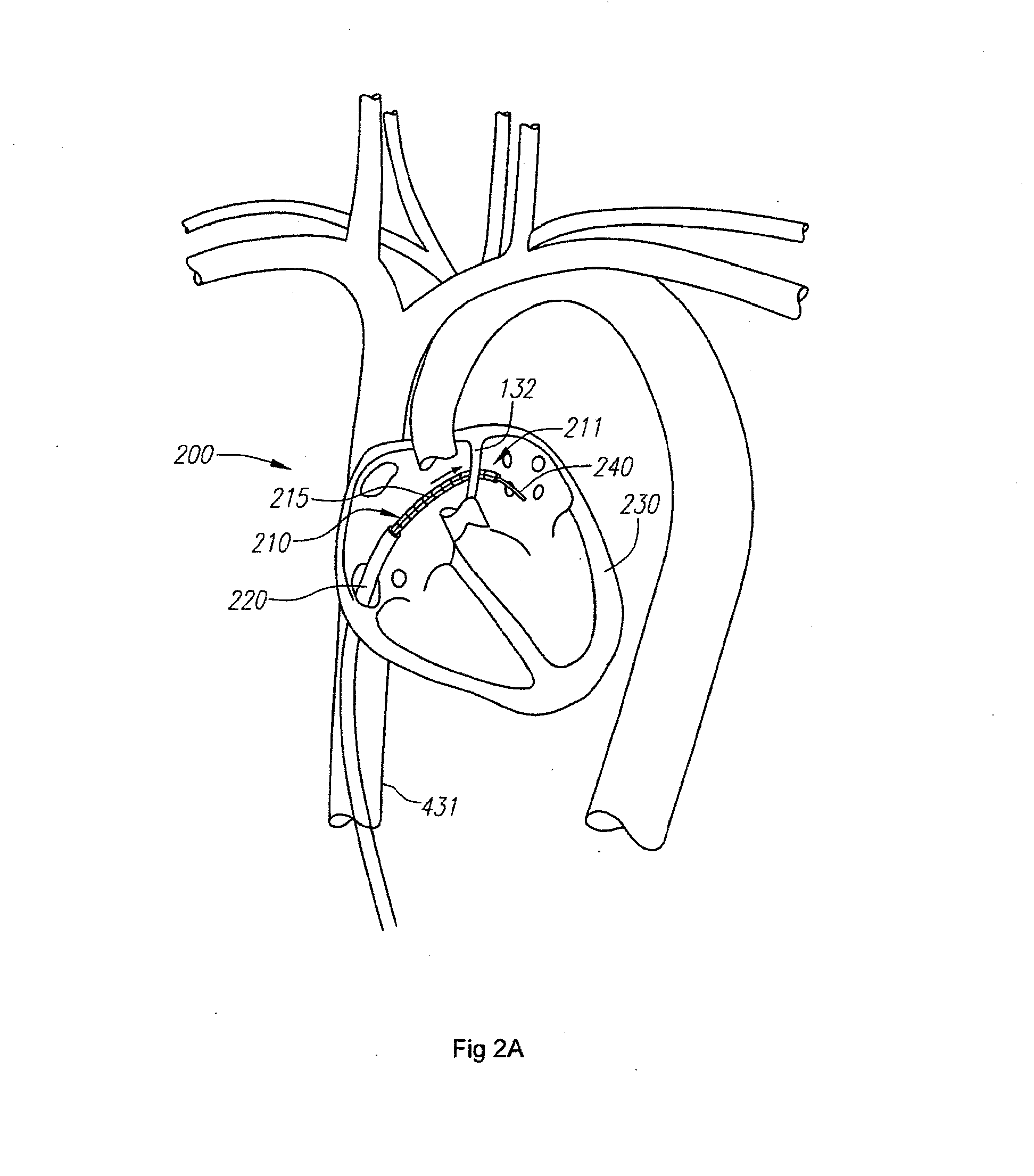
[0055]Referring to FIG. 2A, according to one embodiment, one or more components of a robotically controlled instrument 200 of a robotic surgical system include an optical fiber or fiber sensor 215 (referred to as optical fiber sensor or fiber 215), which is coupled to, or an integral part of, an elongate instrument body 210. Data based on light reflected by gratings of the fiber 215 may be used to determine the shape and / or position of the elongate instrument, which may be a catheter, such as a guide catheter. In the illustrated embodiment, the elongate instrument or catheter 210 is a part of a robotically controlled instrument 200 that it utilized to position a bendable distal end portion 211 of the catheter 210 and one or more wo...


PUM


Abstract

An instrument system that includes an optical fiber and a controller is provided. The optical fiber is coupled to an external structure of a patient and has a strain sensor provided thereon. The controller is operatively coupled to the optical fiber and adapted to receive a signal from the strain sensor and to determine a property of respiration of the patient based on the signal.

Description

CROSS-REFERENCE TO RELATED APPLICATION[0001]The present application is a divisional of U.S. patent application Ser. No. 12 / 192,033 filed on Aug. 14, 2008, which claims the benefit under 35 U.S.C. §119 to U.S. Provisional Application No. 60 / 964,773, filed on Aug. 14, 2007, the contents of which is incorporated herein by reference as though set forth in full.[0002]The present application may also be related to subject matter disclosed in the following applications, the contents of which are also incorporated herein by reference as though set forth in full: U.S. patent application Ser. No. 10 / 923,660, entitled “System and Method for 3-D Imaging”, filed Aug. 20, 2004; U.S. patent application Ser. No. 10 / 949,032, entitled “Balloon Visualization for Transversing a Tissue Wall”, filed Sep. 24, 2005; U.S. patent application Ser. No. 11 / 073,363, entitled “Robotic Catheter System”, filed Mar. 4, 2005; U.S. patent application Ser. No. 11 / 173,812, entitled “Support Assembly for Robotic Catheter...

Claims


Application Information

Patent Timeline
Patent Type & Authority Applications(United States)
IPC IPC(8): A61B5/00A61B18/08
CPCA61B5/06A61B8/00A61B6/12A61B19/2203A61B19/5244A61B19/54A61B2019/2211A61B2019/2223A61B2019/2242A61B2019/2246A61B2019/2273A61B2019/2296A61B2019/442A61B2019/448A61B2019/5236A61B2019/5238A61B2019/5261A61B2019/5276G01B11/16G01B11/165A61B1/00013A61B1/0017A61B1/00057G01L1/242A61B1/00004A61B5/4887A61B8/48A61B5/0064A61B18/082A61B1/00045A61B1/00165A61B5/0059A61B5/7285A61B2034/715A61B90/96A61B34/20A61B34/71A61B2034/301A61B2090/376A61B34/30A61B34/37A61B2034/741A61B34/77A61B90/98A61B2090/374A61B2034/2061A61B2090/378A61B90/39A61B2017/00725A61B5/065A61B5/066A61B2017/00699A61B18/1492A61B1/009A61B18/22A61M2025/0166
Inventor RAMAMURTHY, BHASKAR S.TANNER, NEAL A.YOUNGE, ROBERT G.SCHLESINGER, RANDALL L.
Owner KONINKLIJKE PHILIPS ELECTRONICS NV
Learn More