
Power measuring system

a power measuring system and power measurement technology, applied in powerline communications applications, instruments, electric devices, etc., can solve the problems of increased complexity, increased power consumption in the power measuring system, and increased costs of implementation of the power measuring system

Inactive Publication Date: 2013-04-04
SAMSUNG ELECTRO MECHANICS CO LTD
View PDF1 Cites 5 Cited by
  • Summary
  • Abstract
  • Description
  • Claims
  • Application Information

AI Technical Summary

Benefits of technology

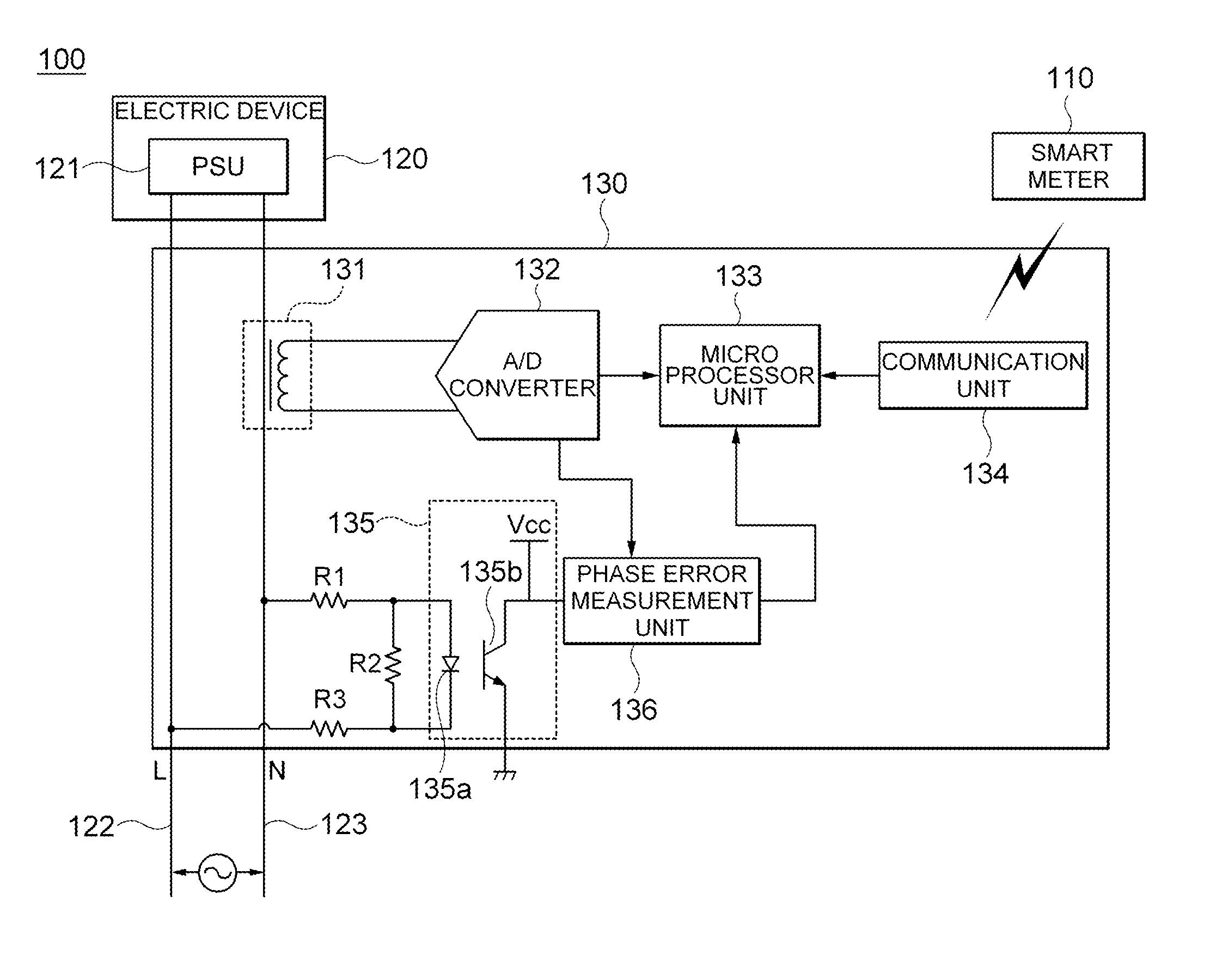
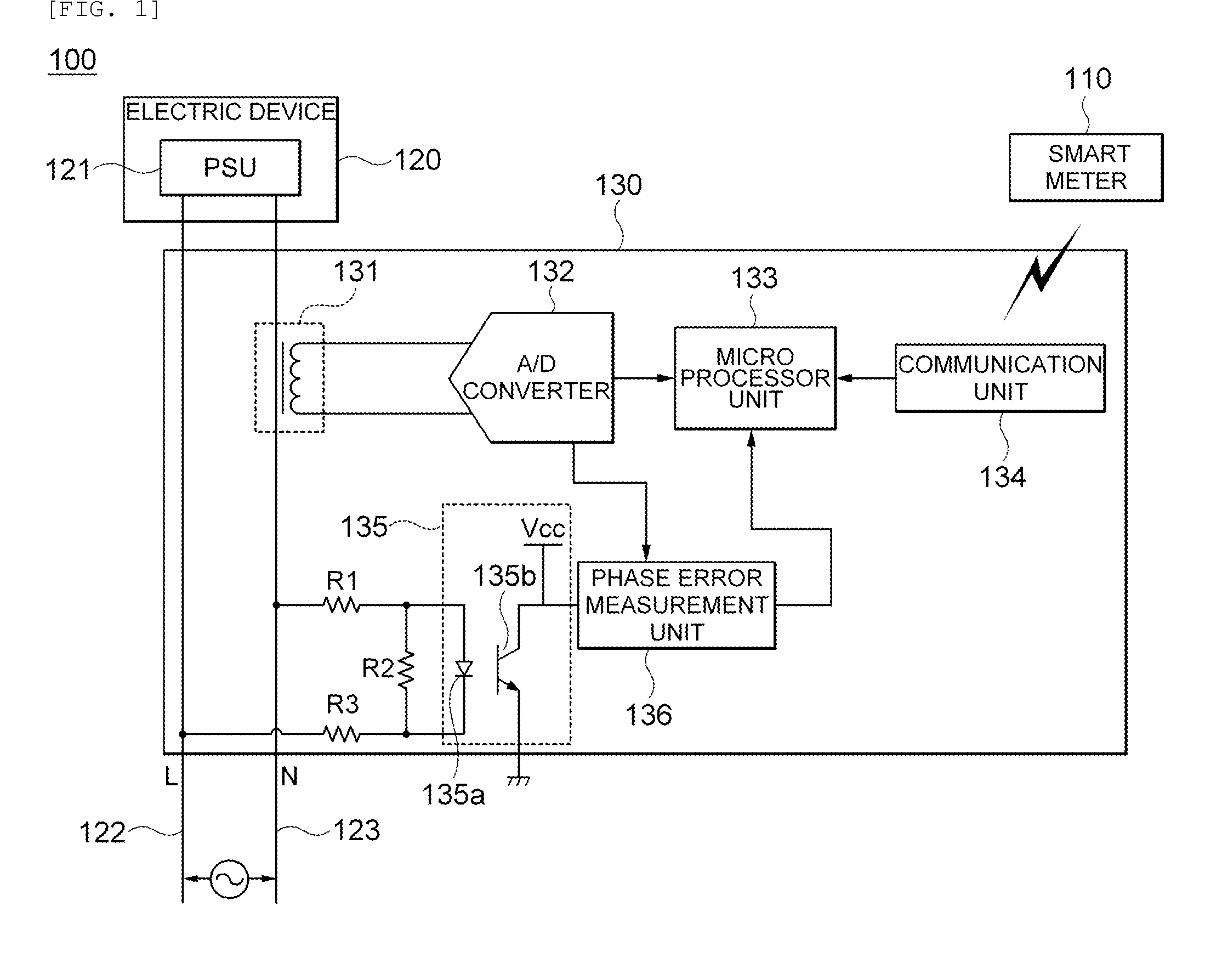
The present invention provides a power measuring system that can measure the power consumption of consumer equipment without using a separate analog-digital converter for voltage. The system includes a smart meter that measures the voltage root mean square value input to the equipment, and a power measurement device that measures the power of the equipment using the voltage root mean square value and the current instantaneous values of the power lines connected to the equipment. The power measurement device includes a current transformer, an analog-digital converter, a communication unit, and a microprocessor unit. The current transformer drops the current instantaneous value of the power lines to a measurable level, and the analog-digital converter converts the current instantaneous value into a digital signal. The communication unit receives the voltage root mean square value measured by the smart meter. The microprocessor unit receives the digital signal and the voltage root mean square value to calculate the power of the equipment. The power measurement system can measure power consumption with high accuracy, which can be useful in managing power consumption and improving energy efficiency.

Problems solved by technology

However, the power measuring system according to the related art requires the high-performance analog-digital converter for each voltage and current so as to calculate the digital signals required for the operation of the microprocessor unit and therefore, much costs to implement the power measuring system are consumed.
As a result, in measuring the power consumption of the consumer equipment, operation may be increased and complicated and thus, the power consumed in the power measuring system may be increased.

Method used


Image

  • Power measuring system
  • Power measuring system
  • Power measuring system

Examples


Embodiment Construction

[0028]Various advantages and features of the present invention and methods accomplishing thereof will become apparent from the following description of embodiments with reference to the accompanying drawings. However, the present invention may be modified in many different forms and it should not be limited to the embodiments set forth herein. These embodiments may be provided so that this disclosure will be thorough and complete, and will fully convey the scope of the invention to those skilled in the art. Like reference numerals throughout the description denote like elements.

[0029]In addition, terms used in the present specification are for explaining the embodiments rather than limiting the present invention. Unless explicitly described to the contrary, a singular form includes a plural form in the present specification. The word “comprise” and variations such as “comprises” or “comprising,” will be understood to imply the inclusion of stated constituents, steps, operations and / ...


PUM


Abstract

Disclosed herein is a power measurement system capable of power of electric devices without performing a quantization process through a separate analog-digital converter for voltage. The power measurement system includes a smart meter measuring a voltage root mean square value input to an electrical device; and a power measurement device measuring power of the electrical equipment using a voltage root mean square value Vrms measured by the smarter meter and a current instantaneous values of power lines connected to the electric device.

Description

CROSS REFERENCE(S) TO RELATED APPLICATIONS[0001]This application claims the benefit under 35 U.S.C. Section 119 of Korean Patent Application Serial No. 10-2011-0100216, entitled “Power Measuring System” filed on Sep. 30, 2011, which is hereby incorporated by reference in its entirety into this application.BACKGROUND OF THE INVENTION[0002]1. Technical Field[0003]The present invention relates to a power measuring system, and more particularly, to a power measuring system measuring power of electrical devices without requiring a separate analog-digital converter for quantizing voltage signals.[0004]2. Description of the Related Art[0005]Power for operating electrical products such as consumer equipment used in a home, business machines used in an office, or the like, is generally supplied by in an order of power plants, transmission lines, and distribution lines that are operated in the Korea Electric Power Corporation.[0006]This power supply method has characteristics of a centralized...

Claims


Application Information

Patent Timeline
Patent Type & Authority Applications(United States)
IPC IPC(8): G06F19/00
CPCG01R21/06H04B2203/5433H04B2203/5408G01R22/06
Inventor LEE, HYUN SUKBAEK, WON JINLEE, YUN HEE
Owner SAMSUNG ELECTRO MECHANICS CO LTD
Learn More