
Bushings, sealing devices, tubing, and methods of installing tubing

a sealing device and tubing technology, applied in the direction of metal working equipment, mechanical equipment, manufacturing tools, etc., can solve the problems of electrical flashover or arc between adjacent systems, thin metal walls are vulnerable to failure, damage to both conductors and any material between

Active Publication Date: 2013-04-11
TITEFLEX
View PDF2 Cites 24 Cited by
  • Summary
  • Abstract
  • Description
  • Claims
  • Application Information

AI Technical Summary

Benefits of technology

The patent text describes various aspects of a bushing and sealing device for connecting tubing. The bushing has one or more axially-extending tongues that can be used to connect the tubing. The bushing can be made from a conductive material, such as metal or metal alloy, and can have a tapered inner surface. The sealing device includes a body member with a sleeve portion and a bushing with one or more tongues that are compressed against the tubing when a nut is tightened. The length of tubing can also include an inner tubing layer and a conductive layer surrounding the inner tubing layer, with the conductive layer being made of metal or metal alloy. The patent text also describes a method of installing energy dissipative tubing. Overall, the invention provides improved methods for connecting and sealing tubing, as well as enhanced energy dissipation capabilities.

Problems solved by technology

Undesirably, the thin metal walls are vulnerable to failure when exposed to physical or electrical forces, such as lightning or fault currents.
This can often result in an electrical flashover or arc between the adjacent systems.
Frequently, the voltage required to breakdown a dielectric material is enough to drive a relatively large amount of energy across the associated spark often resulting in damage to both conductors and any material between them.
The primary mode of failure is extreme heating and melting of these materials.
This leads to the potential for a flashover if the CSST is installed in close proximity to another conductor within a structure and either one becomes energized.
This scenario is worsened by the dielectric jacket that often surrounds CSST.
The result is a reduced capability of the CSST to resist puncture from flashover compared to un-jacketed pipe.

Method used


Image

  • Bushings, sealing devices, tubing, and methods of installing tubing
  • Bushings, sealing devices, tubing, and methods of installing tubing
  • Bushings, sealing devices, tubing, and methods of installing tubing

Examples


Embodiment Construction

Corrugated Tubing

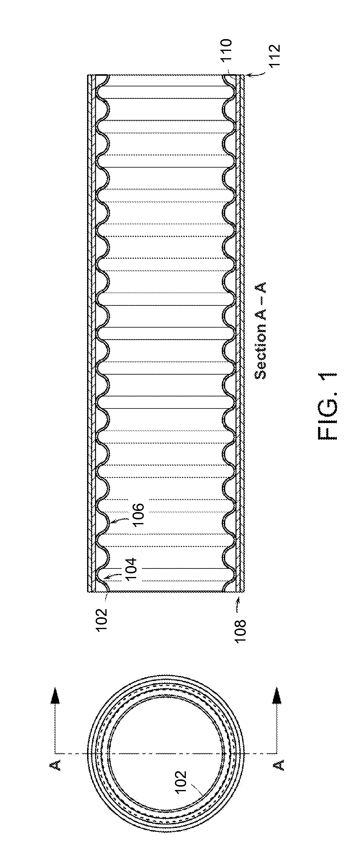
[0049]Referring to FIG. 1, a length of corrugated tubing 102 according to the prior art is provided. The corrugated tubing 102 may be composed of stainless steel or any other suitable material. The tubing 102 contains a number of corrugation peaks 104 and corrugation valleys 106. A jacket 108 (e.g., a multi-layer jacket) covers the outside of the tubing 102.

[0050]The jacket 108 can include a plurality of layers 110, 112. The layers 110, 112 generally form an annulus around the tubing 102, but may have a circular or non-circular cross-section.

Energy Dissipative Tubing

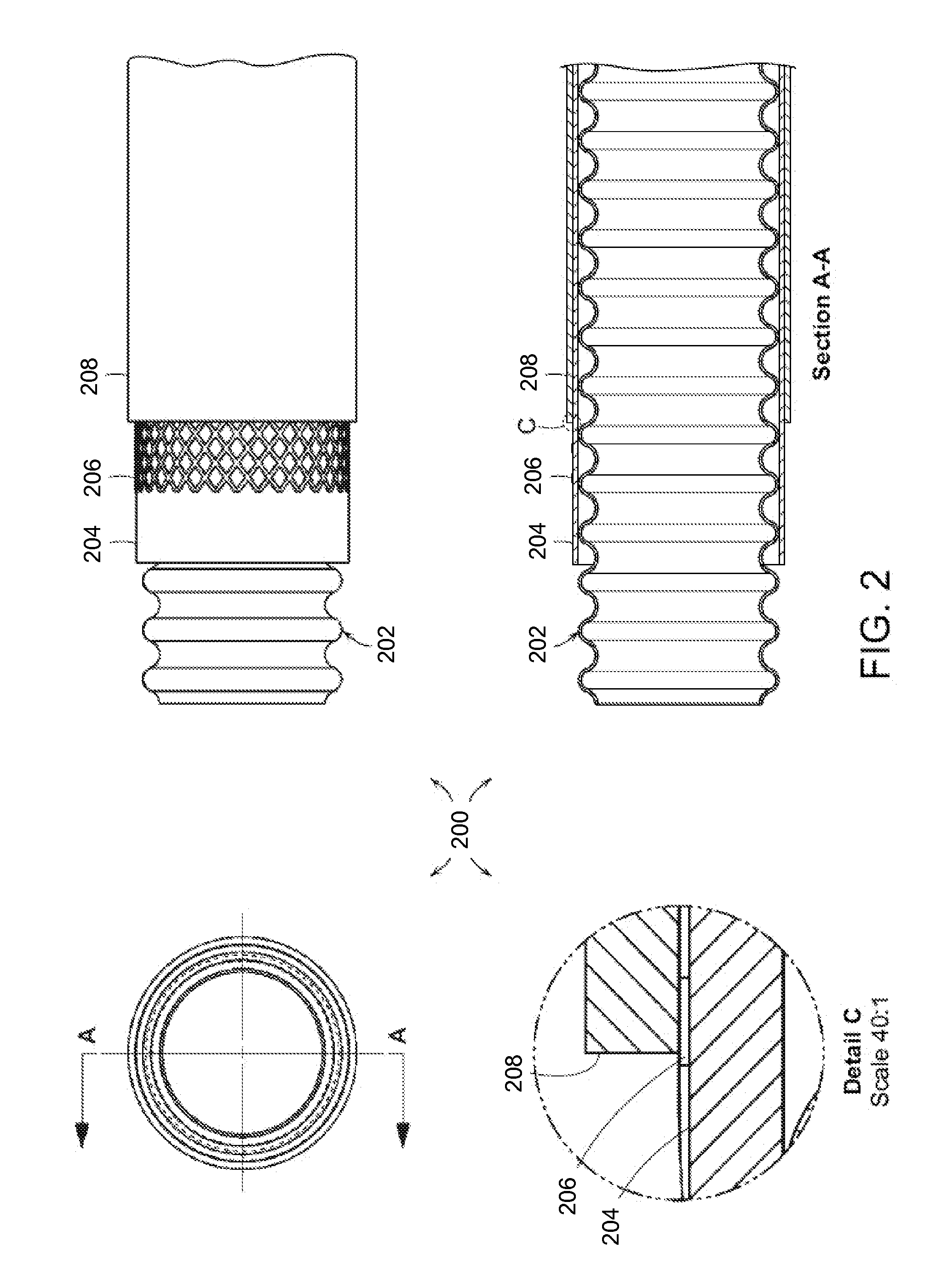
[0051]Referring now to FIG. 2, in order to better absorb energy from fault currents and lightning strikes, energy dissipative jackets are provided that dissipate electrical and thermal energy throughout the respective jackets, thereby protecting the tubing 202. The term “dissipate” encompasses distributing electrical energy to an appropriate grounding device such as a fitting.

[0052]Preferred embodiments ...


PUM

PropertyMeasurementUnit
taper angleaaaaaaaaaa
pressuresaaaaaaaaaa

Abstract

Bushings, sealing devices, tubing, and methods of installing tubing are provided. One aspect of the invention provides a bushing having one or more axially-extending tongues. Another aspect of the invention provides a sealing device for connecting a length of tubing. The sealing device includes a body member defining a sleeve portion and a bushing arranged to be received in the sleeve portion. The bushing includes one or more tongues adapted and configured to be received over at least one layer of the tubing.

Description

CROSS-REFERENCE TO RELATED APPLICATION[0001]This application claims priority to U.S. Provisional Patent Application Ser. No. 61 / 544,516, filed Oct. 7, 2011. The entire contents of this application are hereby incorporated by reference herein.FIELD OF INVENTION[0002]The present invention relates to gas, liquid, and slurry piping systems as well as protective conduit systems for cable carrying purposes, and more particularly to bushings, sealing devices, tubing, methods of installing tubing incorporating fittings capable of transferring and dissipating energy.BACKGROUND OF THE INVENTION[0003]Gas and liquid piping systems utilizing corrugated stainless steel tubing (“CSST”) and fittings are known. Such piping systems can be designed for use in combination with elevated pressures of up to about 25 psi or more and provide advantages over traditional rigid black iron piping systems in terms of ease and speed of installation, elimination of onsite measuring, and reduction in the need for ce...

Claims


Application Information

Patent Timeline
Patent Type & Authority Applications(United States)
IPC IPC(8): H02G3/18H02G1/00
CPCH02G3/0691Y10T29/49826F16L25/0054F16L19/025F16L25/01
Inventor DAUGHTRY, DAVIDSTRUNK, JORDAN
Owner TITEFLEX
Features
  • Generate Ideas
  • Intellectual Property
  • Life Sciences
  • Materials
  • Tech Scout
  • Unparalleled Data Quality
  • Higher Quality Content
  • 60% Fewer Hallucinations
Learn More