Article of clothing comprising an operating part

a technology of operating parts and clothing, which is applied in the direction of electrical appliances, electrical heating, clothing, etc., can solve the problems of water or detergent entering the operating part, easy leakage, and difficult cleaning of such articles of clothing, so as to increase the wearing comfort of the operating part, protect particularly reliably, and be easily established

Inactive Publication Date: 2013-04-11
SIDAS CENT
View PDF15 Cites 12 Cited by
  • Summary
  • Abstract
  • Description
  • Claims
  • Application Information

AI Technical Summary

Benefits of technology

[0014]According to one refinement, the holder of the second molding for the control unit is designed as a depression in the second molding. This depression can, for example, be covered by a protective film or a protective cover. A control unit located in the depression can thus be protected from outside influences, for example from moisture, splashing water, dirt or mechanical effects. In addition, such a protective film or such a protective cover can prevent the control unit from inadvertently detaching from the second molding and potentially being lost. On the whole, such a protective film or such a protective cover can thus assure particularly secure storage of the control unit, for example during cleaning of the article of clothing or during replacement of the control unit.
[0015]According to one refinement, the first molding has a flange-shaped first edge region and the second molding has a flange-shaped second edge region. When and as soon as the two moldings are connected to each other (by the aforementioned mutual engagement of the retaining elements of the two moldings), these flange-shaped edge regions rest on top of each other in a planar manner and extend completely, which is to say without interruptions, around the holder for the control unit. The two edge regions are preferably additionally pressed against each other by a permanent pressing force which is generated by the two retaining elements. Such planar seating on top of each other, and optionally pressing against each other, of the two flange-shaped edge regions causes particularly secure sealing of the holder of the control unit, so that the same is protected particularly reliably, for example from entering liquid. So as to generate the aforementioned pressing force, all or at least some of the retaining elements are designed to be elastic. For this purpose, the retaining elements in question can be produced from a flexible and permanently elastic plastic material, such as a silicone, for example. Materials that can be used for the operating part, and more particularly for the first and / or second moldings and / or the retaining elements of the first and / or second moldings include all castable, pressable, extrudable, moldable and / or blow-moldable materials, such as thermoplastic elastomers (TPE), thermoplastic (poly)urethanes (TPU), and rubber-like materials. The parts in question can thus be cast, pressed, extruded, molded or blow-molded from these materials. It is also possible, of course, to produce the first and / or second moldings entirely from such a permanently elastic material. The aforementioned protective film and the aforementioned protective cover can likewise be produced from an elastic material, for which the above-mentioned materials may also be used. The use of (permanently) elastic materials can additionally increase the wearing comfort of the operating part and of the article of clothing. By using elastic materials, it is also possible for the connection between the first molding and the second molding to be established particularly easily and to be detached again.
[0016]According to one refinement, the second molding has a hole for passing the aforementioned electrical wires, such as the control line, for example, through the second molding. It can thus be prevented that the aforementioned wires must be passed through an interface or a boundary region between the first and second moldings, whereby the risk of leaks between the first and second moldings is reduced.
[0017]The risk of leaks can also be reduced by means of additional sealing elements, which preferably have an annular design and preferably extend completely around the receiving region for the control unit. Such a sealing element can, for example, be designed in form of a rib on one of the two moldings or by a separate sealing ring.

Problems solved by technology

While such an operating part allows a device of an article of clothing to be conveniently operated, cleaning such articles of clothing has proven to be problematic.
This is because of the risk of water or detergent entering the operating part when cleaning the article of clothing and damaging the control unit.
Especially the site at which a control line passes through the encapsulation of the control unit for transmitting control signals from the control unit to the device represents a weak point in this regard, because leaks can easily develop at this site in particular.

Method used


Image

  • Article of clothing comprising an operating part
  • Article of clothing comprising an operating part
  • Article of clothing comprising an operating part

Examples


Embodiment Construction

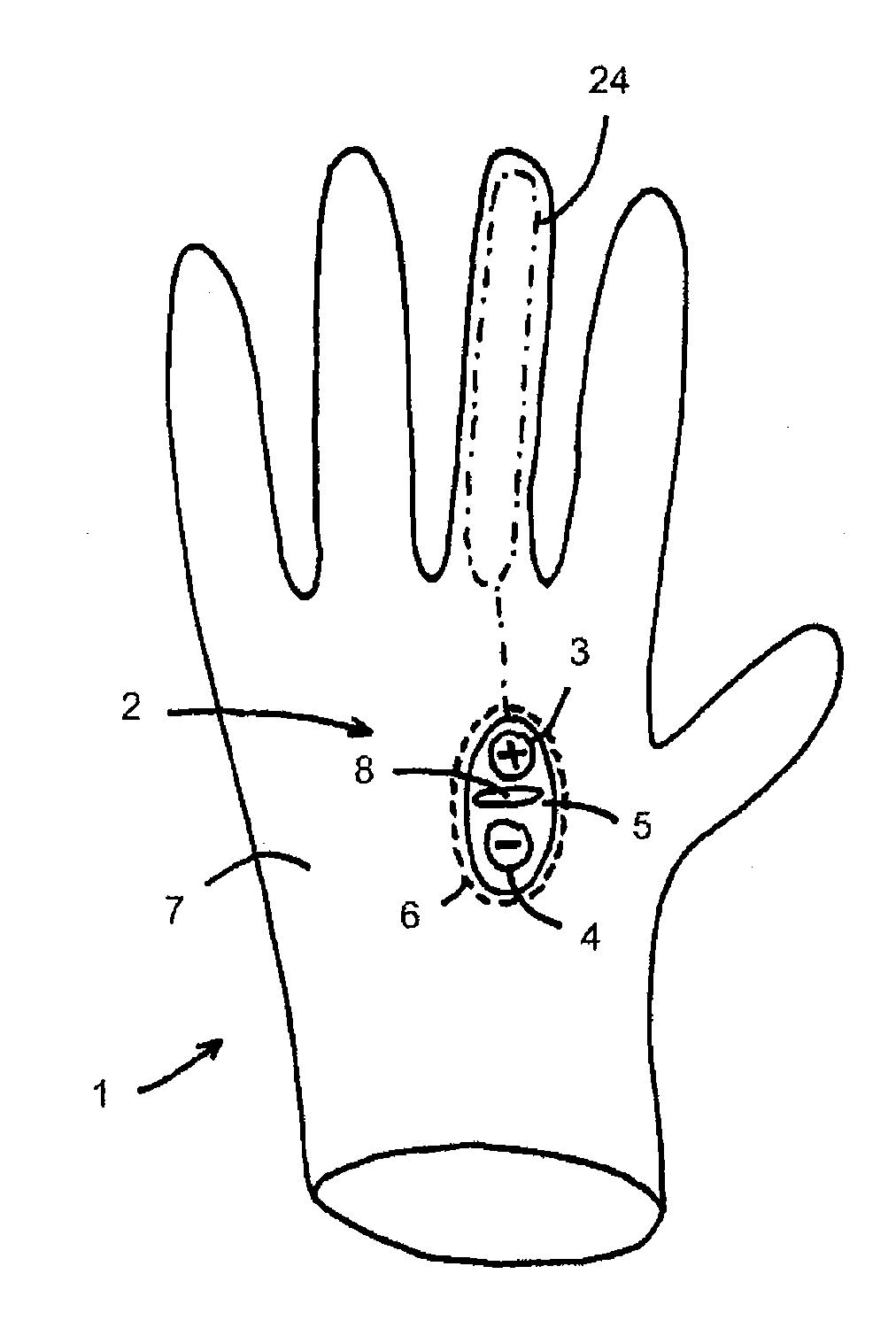
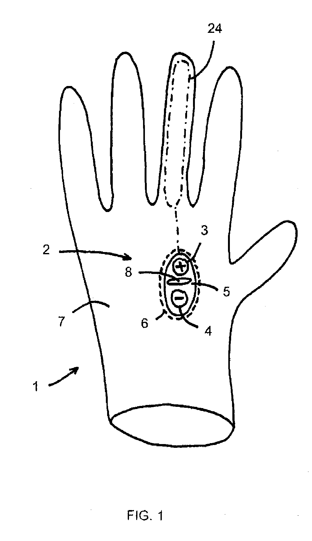
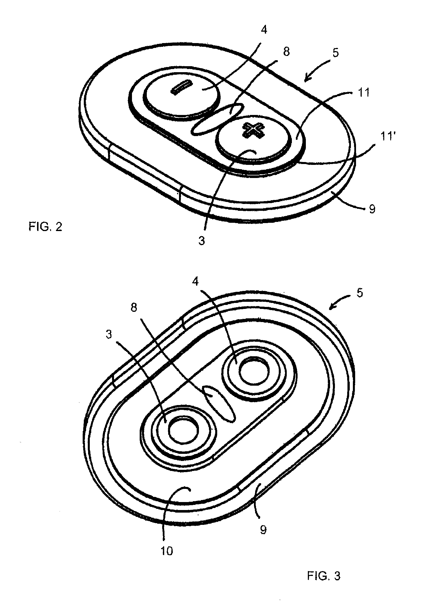
[0030]FIG. 1 shows a schematic illustration of a special exemplary embodiment of an article of clothing 1 of the type that is proposed here. The article of clothing 1 is a glove, comprising an operating part 2 for manually operating a controllable heating device 24 which is connected to the article of clothing 1 by means of a first and a second operating element 3, 4. The heating device 24 is only schematically indicated inside the article of clothing 1 by a dot-and-dashed line to provide better clarity. Reference is made here to the prior art, for example to the published prior art WO 2009 / 092618 A1, with regard to details for possible embodiments of the heating device 24. The two operating elements 3, 4 are disposed on the first molding 5 of the operating part, which is rigidly connected to an outer shell 7 of the article of clothing 1 by means of a seam 6 and comprises a transparent region 8 through which a display of a control unit is visible, refer to FIG. 6.

[0031]The article o...


PUM


Abstract

An article of clothing, comprising an operating part for manually operating a controllable device which can be connected to the article of clothing by means of at least one operating element of the operating part, wherein the operating part comprises a first molding, which is rigidly connected to the article of clothing and which comprises the at least one operating element, and a second molding, which comprises a holder for a control unit of the device and can be connected to the first molding, wherein the first molding comprises at least one first retaining element and the second molding comprises at least one second retaining element, wherein the two retaining elements can be brought in mutual engagement with each other so as to establish a detachable connection between the first molding and the second molding.

Description

RELATED APPLICATION[0001]This application claims the benefit, under 35 U.S.C. 119(e), of the provisional application filed Oct. 7, 2011 under 35 U.S.C. 111(b), which was granted Ser. No. 61 / 544,392. This provisional application is hereby incorporated by reference.BACKGROUND OF THE INVENTION[0002]The invention, relates to an article of clothing, and more specifically to an article of clothing comprising controllable devices.[0003]Such articles of clothing of the type in question comprising controllable devices are known from the published prior art WO 2009 / 092618 A1. This document describes such an article of clothing in one embodiment in the form of a glove comprising a heating device. An article of clothing of the type in question comprises an operating part having one or more operating elements, such as one or more push buttons, for example, so as to manually operate the controllable device thereof. A control unit of the device can be operated via the at least one operating elemen...

Claims


Application Information

Patent Timeline
Patent Type & Authority Applications(United States)
IPC IPC(8): H05B3/00
CPCH05B3/00A41D19/0024A41D1/002
Inventor KREMER, GERHARDMARON, URS
Owner SIDAS CENT
Why Eureka
Try Eureka