Temperature controlling surfaces and support structures

a technology of temperature control surface and support structure, which is applied in the direction of indirect heat exchangers, lighting and heating apparatus, laminated elements, etc., can solve the problems of ongoing heat removal, relatively poor conductivity of polymeric or plastic films, etc., and achieve the effect of preventing or minimizing the loss of liquid coolan

Active Publication Date: 2013-04-11
GLOBAL LIFE SCI SOLUTIONS USA LLC
View PDF3 Cites 58 Cited by
  • Summary
  • Abstract
  • Description
  • Claims
  • Application Information

AI Technical Summary

Benefits of technology

[0012]Yet another embodiment the invention is a jacketed, tiered baffle, bioreactor tank comprising: an outer cylindrical-shaped jacket; and a cylindrical tank having an inner tank surface defining a chamber configured for supporting a flexible bag disposed within the chamber, and an outer tank surface having tiered baffles configured for routing a liquid coolant around the entirety of the outer ta

Problems solved by technology

However, in single-use bioprocessing bags, heat removal is an ongoing problem, especially for microbial bioreactors.
As is well known by those of skill

Method used


Image

  • Temperature controlling surfaces and support structures
  • Temperature controlling surfaces and support structures
  • Temperature controlling surfaces and support structures

Examples


wand embodiment

[0102]FIG. 4A is a cross-sectional side view of an exemplary reactor system 400 having at least one heat exchanger module 404 wherein the heat exchange module 404 comprises a wand-like body 406, the bottom portion 424 of which is configured to conform to the shape of the support structure 402. The body 406 can be disposed vertically between an outer support structure 402 and the interior of the inner container 408, as shown, using a coupler 410 and can be elongate to extend at least a substantial portion of the distance between the top 412 and bottom 414 of the support structure 402.

[0103]Disposed within the body 406, a heat exchanger 416 can produce a fluid flow path for a temperature control fluid to circulate through the heat exchange module 404. The heat exchanger can be in fluid communication with a temperature control fluid source and have an inlet 420 and an outlet 418. Furthermore, the body 406 can include a thermally conductive surface 422 that is in thermal communication w...

liner embodiment

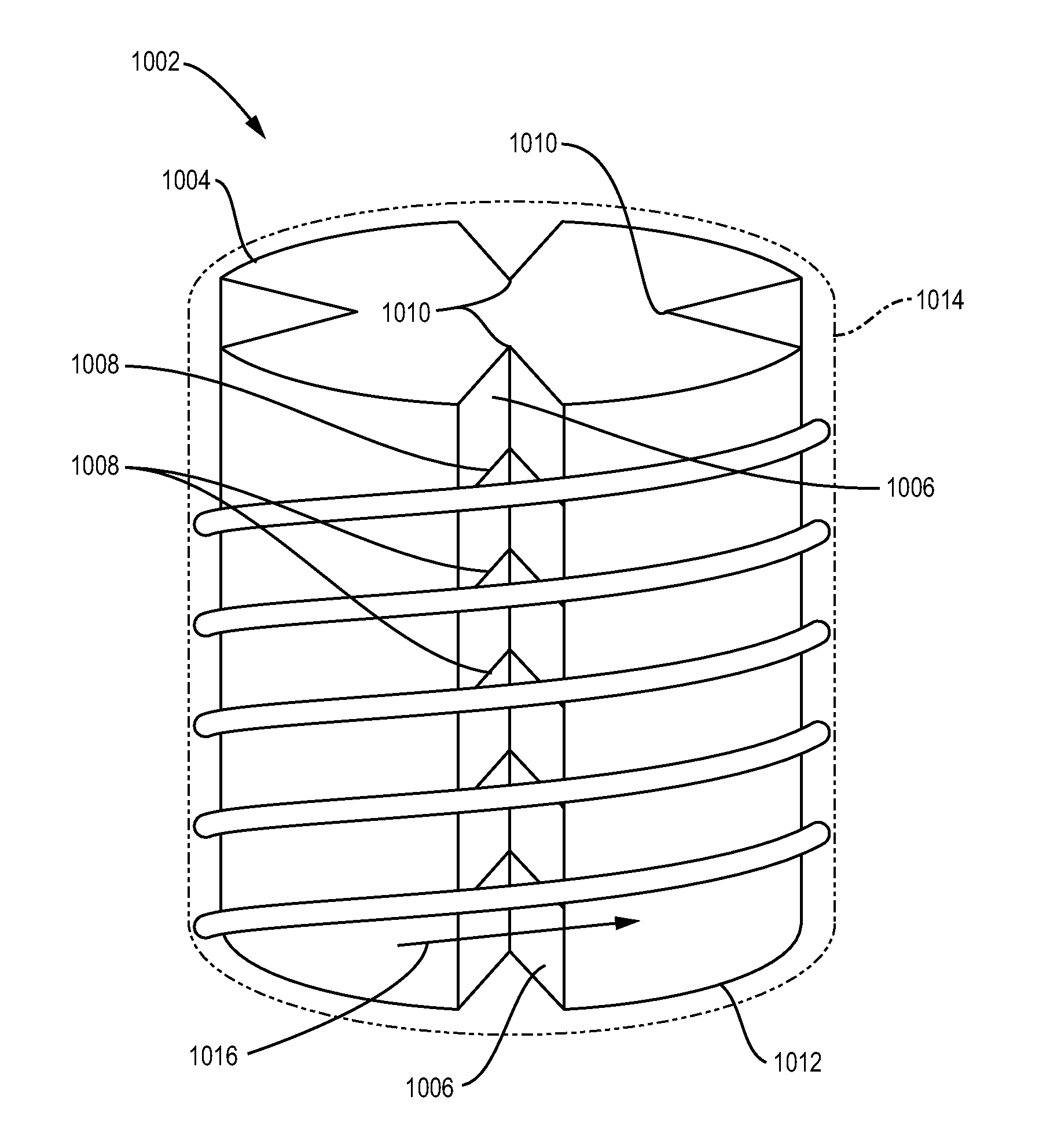
[0117]As shown in FIG. 13, some embodiments of the heat exchange module 1300 can comprise a removable, non-integral liner 1304 that can be disposed between an inner container 1302 and an outer support structure 1306. In some embodiments, the liner 1304 can be formed of a flexible material. Alternatively, the liner can be a non-collapsible liner. For instance, the liner 1304 can be made of a semi-rigid material cylindrically formed. The liner 1304 can be maintained between an inner reactor vessel or container 1302 and the outer support structure 1306 by any suitable method such as by friction, pressure (for example, pressure exerted on the surfaces upon expansion of the collapsible bag), gravity, fastening with screws, pegs, clamps, or the like, and use of adhesives. The liner 1304 can include a temperature control fluid inlet 1308 and outlet 1310, which can be fed through ports 1314 and 1316.

[0118]The liner can have channel segments 1312 creating a non-linear flow path between the i...


PUM


Abstract

A heat exchange module for use in a chemical, pharmaceutical or biological reactor system can include a body configured to be disposed in the reactor system having an inner replaceable reactant container is disclosed. The body can further include at least one thermally conductive surface adapted to contact the inner replaceable reactant container to facilitate heat transfer. Furthermore, the heat exchange module can include a heat exchanger disposed within the module body and can include a fluid circulation path through which a heat exchange fluid can be circulated.

Description

RELATED APPLICATIONS[0001]This application claims the priority benefit of U.S. Provisional Application Nos. 61 / 566,187 filed on Dec. 2, 2011, and 61 / 586,398 filed on Jan. 13, 2012, the teachings of each are incorporated herein by reference in their entirety. This application is also a continuation-in-part of U.S. patent application Ser. No. 12 / 410,724 filed Mar. 25, 2009, which claims the priority benefit of U.S. Provisional Application No. 61 / 039,382 filed on Mar. 25, 2008, the teachings of each are also incorporated herein by reference in their entirety.FIELD OF INVENTION[0002]This disclosure relates generally to biochemical processing systems and methods and, in particular, to systems for controlling temperature of a reactor vessel.BACKGROUND[0003]A variety of vessels for manipulating fluids and / or for carrying out chemical or biological reactions are available. For example, biological materials such as mammalian, plant or insect cells and microbial cultures can be processed usin...

Claims


Application Information

Patent Timeline
IPC IPC(8): C12M1/02B01F15/00
CPCC12M41/24F28F2013/006C12M23/14F28F2255/02B01J19/006B01J19/18B01J2219/0002B01J2219/00081B01J2219/00085B01J2219/0009B01J2219/00768F28F3/12F28F13/06F28D1/06F28D2021/0077F28D2021/0078F28D1/0213B01F15/0085B01J2219/00094B01J2219/00765C12M23/28C12M27/20C12M41/18F28D7/024F28D7/026B01J19/24B01J2219/24B65D31/02C12M23/26F16L11/04F28D1/047F28D2021/0022F28F9/0131F28F2009/228B01F35/513
Inventor DAMREN, RICHARD L.ERDENBERGER, THOMASTUOHEY, COLIN R.CROWELL, JOSEPH D.GALLIHER, PARRISH M.CLAPP, KENNETH P.MITCHELL, PETER A.
Owner GLOBAL LIFE SCI SOLUTIONS USA LLC
Why Eureka
Try Eureka