Manual emergency resuscitator with pre-defined volume control

a volume control and emergency resuscitation technology, applied in respirators, other medical devices, medical devices, etc., can solve the problems of inability to guarantee the consistency of the volume of air, add additional stress to what is normally an already chaotic and stressful situation, and deficiency in prior technology

Active Publication Date: 2013-04-18
PEARCE RICHARD S
View PDF6 Cites 13 Cited by
  • Summary
  • Abstract
  • Description
  • Claims
  • Application Information

AI Technical Summary

Benefits of technology

[0012]An object of the invention is to provide a resuscitator that allows the user to deliver a precise volume of air to ventilate a patient no matter what hand size or hand strength the rescuer may possess.

Problems solved by technology

Current resuscitator designs work relatively well and have saved countless lives; however, there is a deficiency in the prior technology.
When a user squeezes the silicone rubber bladder, there is no guarantee regarding the consistency of the volume of air that is being delivered to the patient with each squeezing cycle.
This shortfall in the prior art requires an emergency vehicle has to carry three different bladder assemblies with them at any time, and finding the correct size for the situation can add additional stress to what is usually an already chaotic and stressful situation.
By use of an elongated leg member, Holt fails to provide a compact resuscitator.
Moreover, Holt's elongated leg member may become fouled or tangled during the rush and chaos of emergency use.
The unwieldy mechanical configuration of Kitrell prevents quick use in tight quarters.
The string and ball system of the '167 patent creates a awkward vertical height to the apparatus and prevent quick one handed volume adjustments.

Method used


Image

  • Manual emergency resuscitator with pre-defined volume control
  • Manual emergency resuscitator with pre-defined volume control
  • Manual emergency resuscitator with pre-defined volume control

Examples


Embodiment Construction

[0021]Detailed descriptions of the preferred embodiment are provided herein. It is to be understood, however, that the present invention may be embodied in various forms. Therefore, specific details disclosed herein are not to be interpreted as limiting, but rather as a basis for the claims and as a representative basis for teaching one skilled in the art to employ the present invention in virtually any appropriately detailed system, structure or manner.

REFERENCE NUMBERS

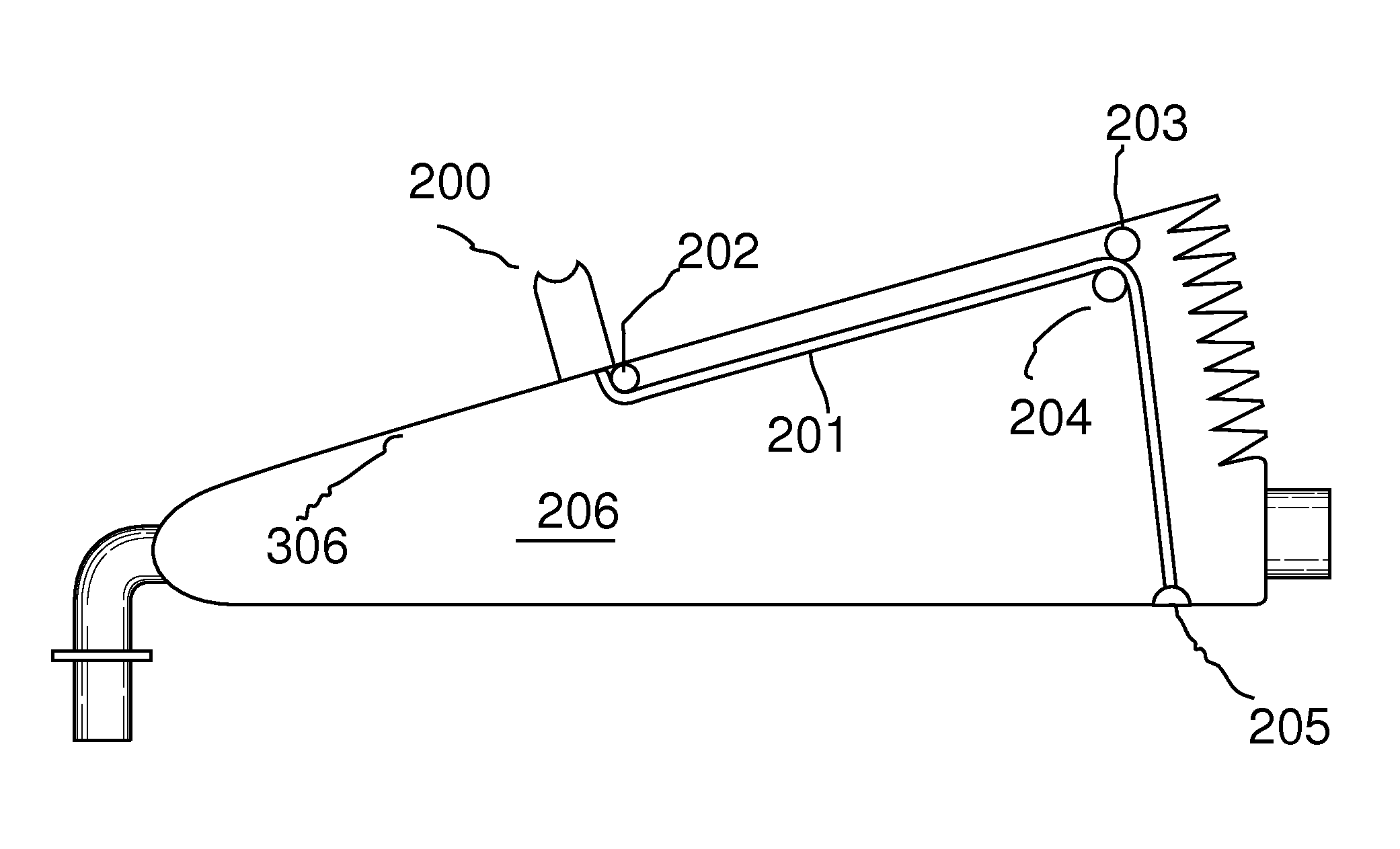
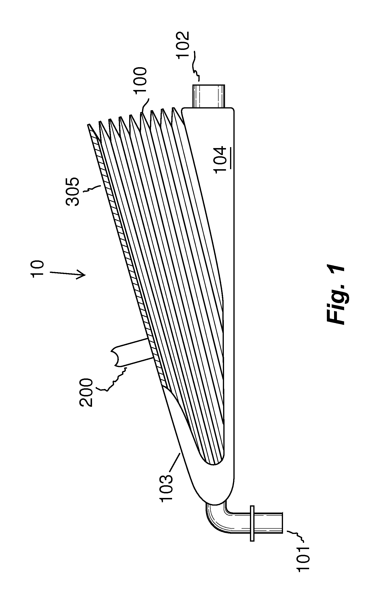
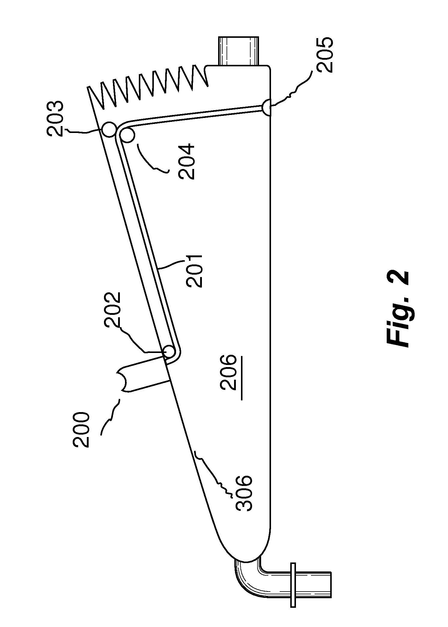
[0022]10 a disclosed embodiment in general[0023]100 accordion section[0024]101 air exit value[0025]102 oxygen input value[0026]103 front hinge assembly[0027]104 lower housing assembly[0028]200 volume selector[0029]201 volume selector cord[0030]202 first cord pivot pin[0031]203 second cord pivot pin[0032]204 third cord pivot pin[0033]205 cord anchor[0034]206 accordion chamber[0035]207 index pin of volume selector 200[0036]300 selection void defined by an upper plate[0037]301 closed position[0038]302 infant position[00...


PUM


Abstract

A manual emergency resuscitator uses a volume control system having pre-defined setting to accommodate patients of different sizes. An upper plate 305 is attached to a front hinge assembly 103 and a lower housing assembly is attached to the front hinge assembly. The lower housing assembly defines the lower portions of an accordion chamber 206. A selection void 300 is defined within the upper plate 305, with the selection void further defined by voids indexed to a closed position, infant position, child position and an adult position. A volume selector cord 201 has a first end attached to a volume selector, with the volume selector contained within the selection void. Placing the volume selector into one of the predefined positions regulates the amount of air delivered by the resuscitator.

Description

[0001]RELATED PATENT APPLICATION AND INCORPORATION BY REFERENCE[0002]This is a Continuation in Part (CIP) utility patent application based upon U.S. patent application Ser. No. 12 / 386,255 filed on or about Apr. 16, 2009. This related application is incorporated herein by reference and made a part of this application. If any conflict arises between the disclosure of the invention in this utility application and that in the related application, the disclosure in this utility application shall govern. Moreover, the inventor incorporates herein by reference any and all patents, patent applications, and other documents hard copy or electronic, cited or referred to in this application.BACKGROUND OF THE INVENTION[0003](1) Field of the Invention[0004]This invention relates generally to the field of emergency resuscitators and more specifically to manual resuscitators adaptable patients of different sizes.[0005](2) Description of the Related Art[0006]Resuscitators are known by health care an...

Claims


Application Information

Patent Timeline
Patent Type & Authority Applications(United States)
IPC IPC(8): A61M16/20
CPCA61M16/20A61M16/0075A61M16/0084A61M16/10A61M2202/0208A61M16/0078
Inventor PEARCE, RICHARD S.
Owner PEARCE RICHARD S
Why Eureka
Try Eureka