
Transition nozzle

Active Publication Date: 2013-04-18
GENERAL ELECTRIC CO
View PDF7 Cites 7 Cited by
  • Summary
  • Abstract
  • Description
  • Claims
  • Application Information

AI Technical Summary

Benefits of technology

This patent text describes a new design for a transition nozzle, which is a part of a gas turbine engine. The nozzle is designed to direct the flow of combustion products towards a turbine bucket stage. The design includes a liner with specific features that guide the flow of the combustion products, such as a flow contouring feature or a non-axisymetric feature. The nozzle is also designed to be coupled to a compressor and combustor stage, which can improve the efficiency of the engine. Overall, the design helps to optimize the flow of the combustion products and increases power generation from the gas turbine engine.

Problems solved by technology

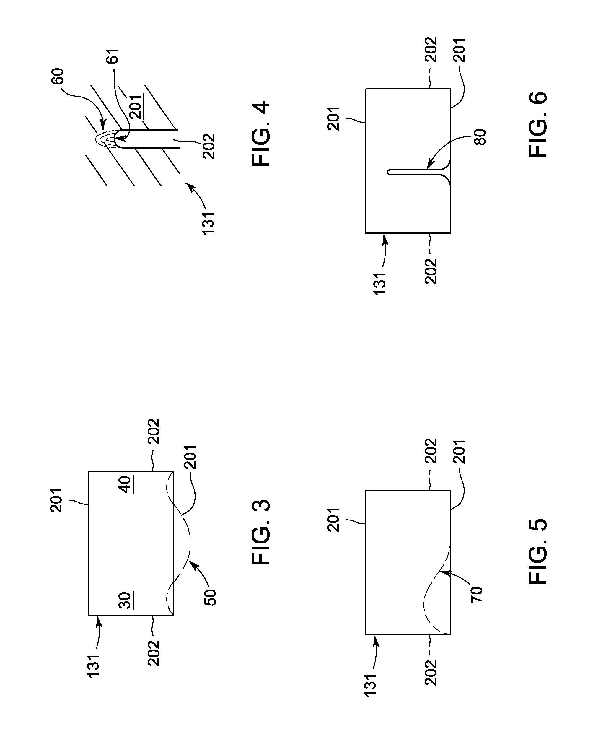
This can negatively impact the stage efficiency and has led to development of non-axisymetric endwall contouring (EWC), which has been effective in reducing secondary flow losses for turbines.

Method used


Image

  • Transition nozzle
  • Transition nozzle
  • Transition nozzle

Examples


Embodiment Construction

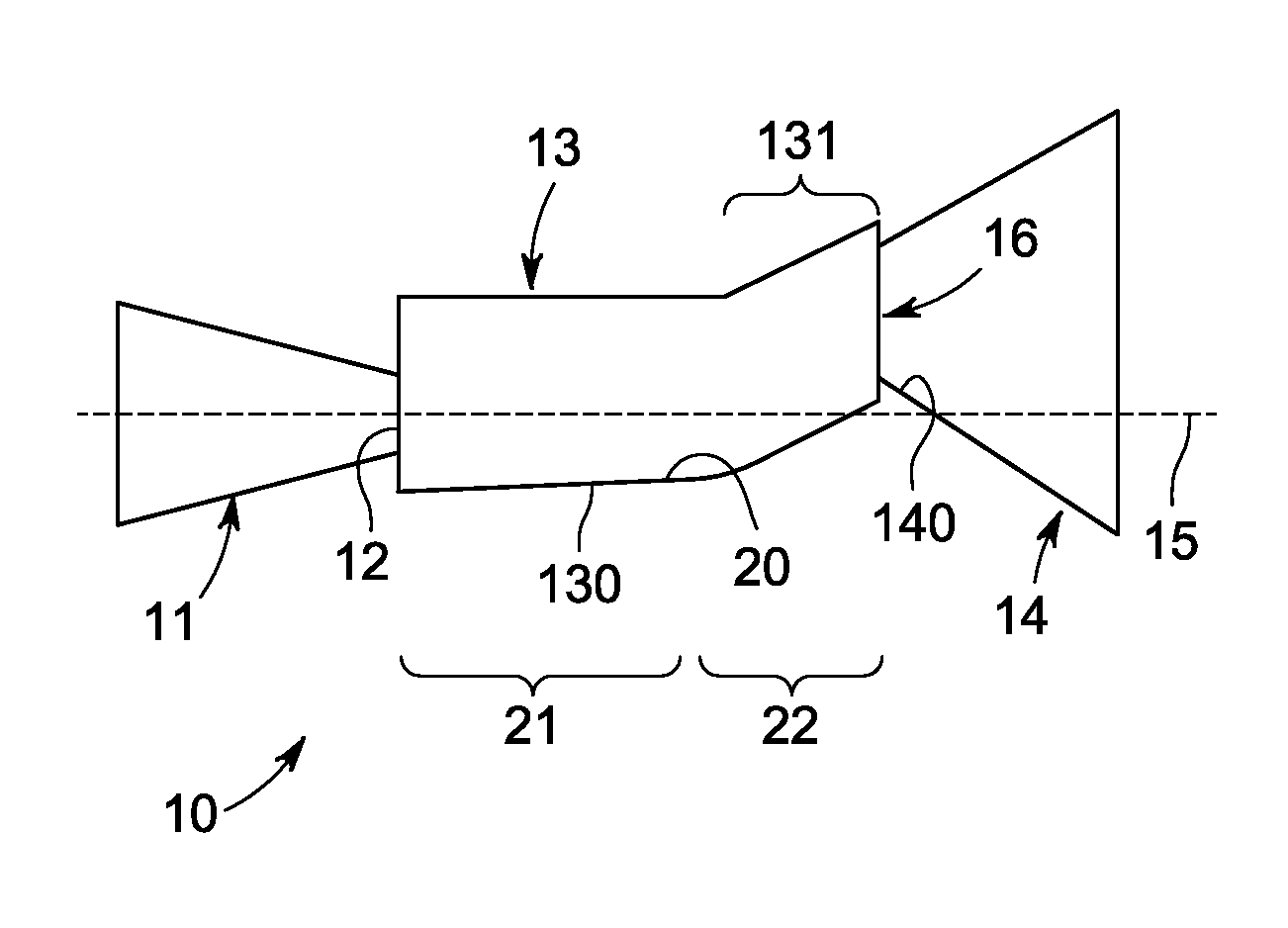
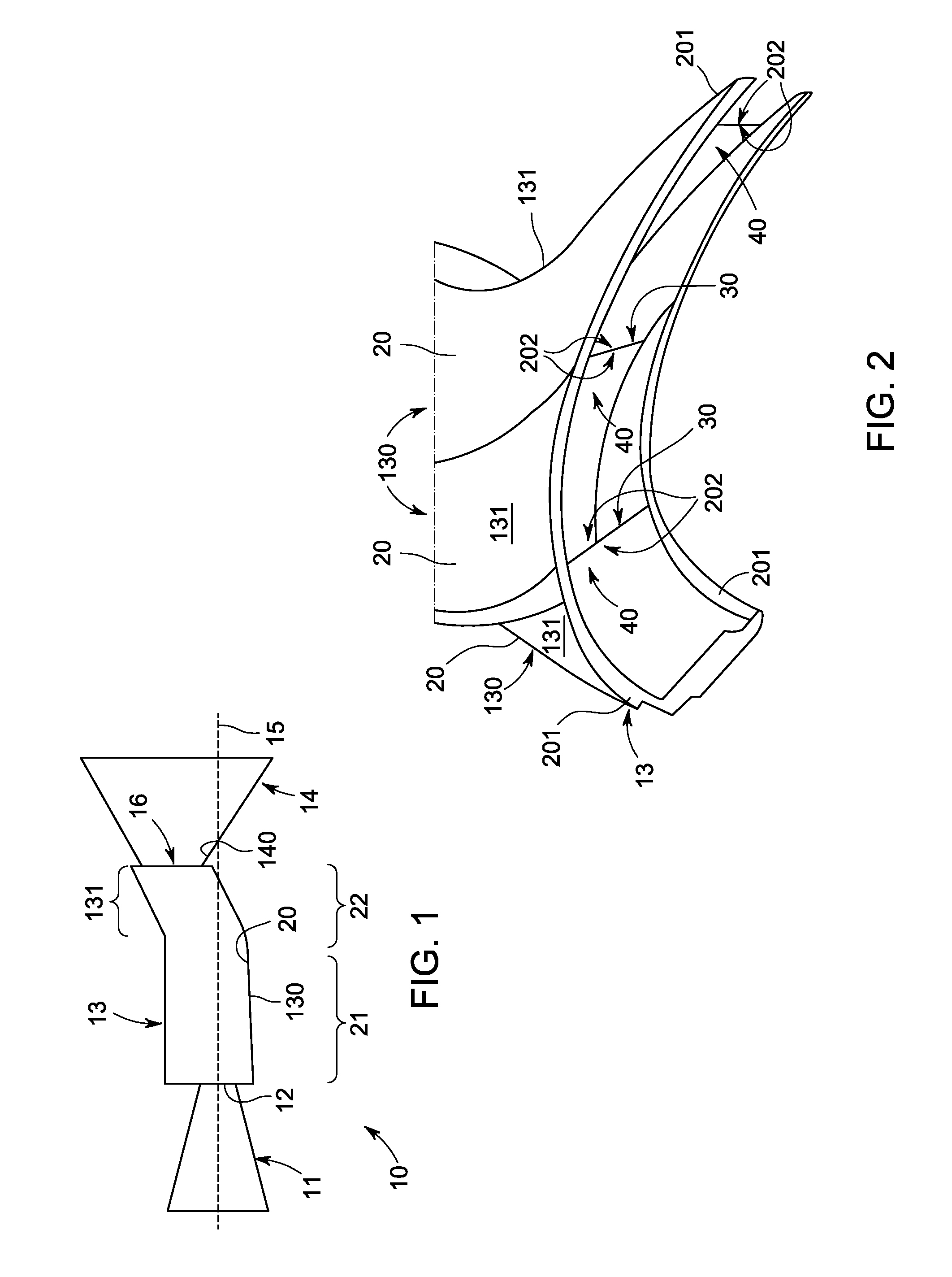
[0017]With reference to FIGS. 1 and 2, a gas turbine engine 10 is provided and includes a compressor 11 having an outlet 12 through which compressed flow passes, a combustor stage 13 coupled to the outlet 12 and a turbine 14. The combustor stage 13 is receptive of the compressed flow via the outlet 12 and includes a combustor 130 in an interior of which combustible materials are mixed and combusted with the compressed flow output from the compressor 11 to produce exhaust. The turbine 14 is coupled to the combustor stage 13 and is receptive of the exhaust produced in the combustor 130 for power and / or electricity generation. A portion 131 of the combustor 130 is oriented tangentially with respect to an engine centerline 15 and includes a non-axisymetric flow contouring feature 16.

[0018]In a typical gas turbine engine, the combustor would be aligned with the engine centerline and a first stage of the turbine would be provided as a nozzle (i.e., the stage 1 nozzle) having airfoils that...


PUM


Abstract

A transition nozzle is provided and includes a liner in which combustion occurs and through which products of the combustion flow toward a turbine bucket stage. The liner includes opposing endwalls and opposing sidewalls extending between the opposing endwalls. The opposing sidewalls are oriented to tangentially direct the flow of the combustion products toward the turbine bucket stage. At least one of the opposing endwalls and the opposing sidewalls including a flow contouring feature to guide the flow of the combustion products.

Description

BACKGROUND OF THE INVENTION[0001]The subject matter disclosed herein relates to a transition nozzle and, more particularly, a transition nozzle having non-axisymetric endwall contouring.[0002]Typical gas turbine engines include a compressor, a combustor and a turbine. The compressor compresses inlet gas and includes and outlet. The combustor is coupled to the outlet of the compressor and is thereby receptive of the compressed inlet gas. The combustor then mixes the compressed gas with combustible materials, such as fuel, and combusts the mixture to produce high energy and high temperature fluids. These high energy and temperature fluids are directed to a turbine for power and electricity generation.[0003]Generally, the combustor and the turbine would be aligned with the engine centerline. A first stage of the turbine would thus be provided as a nozzle (i.e., the stage 1 nozzle) having airfoils that are oriented and configured to direct the flow of the high energy and high temperatur...

Claims


Application Information

Patent Timeline
IPC IPC(8): F01D1/02
CPCF01D9/023F01D5/145
Inventor STEIN, ALEXANDERSIDEN, GUNNAR LEIF
Owner GENERAL ELECTRIC CO
Learn More