
Floor tile with overmold crush pads

a technology of overmolding and crush pads, which is applied in the field of floor tiles, can solve the problems of increasing the cost of manufacturing the resultant tile, the difficulty of manufacturing an injection-molded plastic tile with two or more perceptible colors per tile, etc., and achieves the effect of reducing the coefficient of friction and reducing the rigidity

Inactive Publication Date: 2013-04-18
MACNEIL IP
View PDF12 Cites 37 Cited by
  • Summary
  • Abstract
  • Description
  • Claims
  • Application Information

AI Technical Summary

Benefits of technology

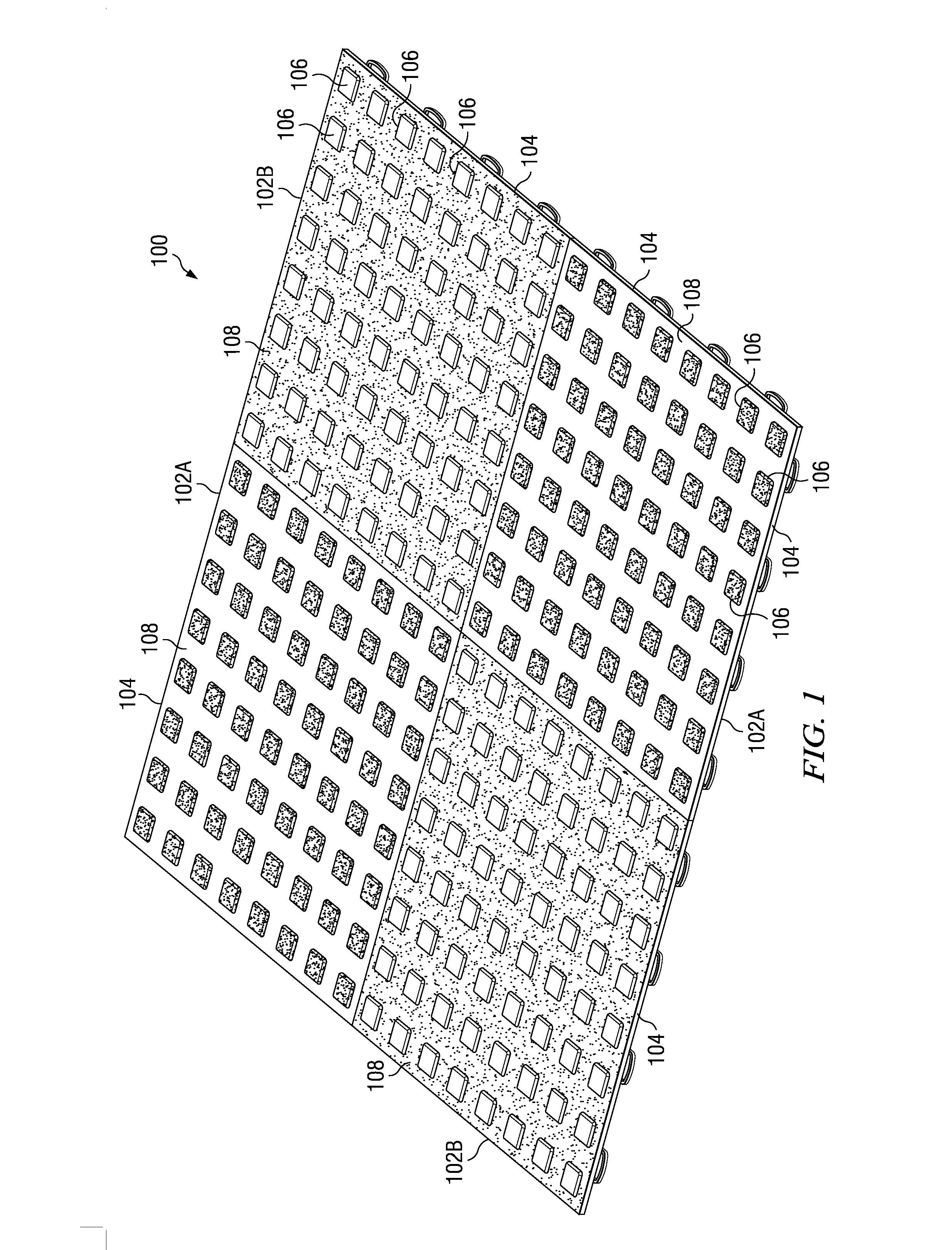
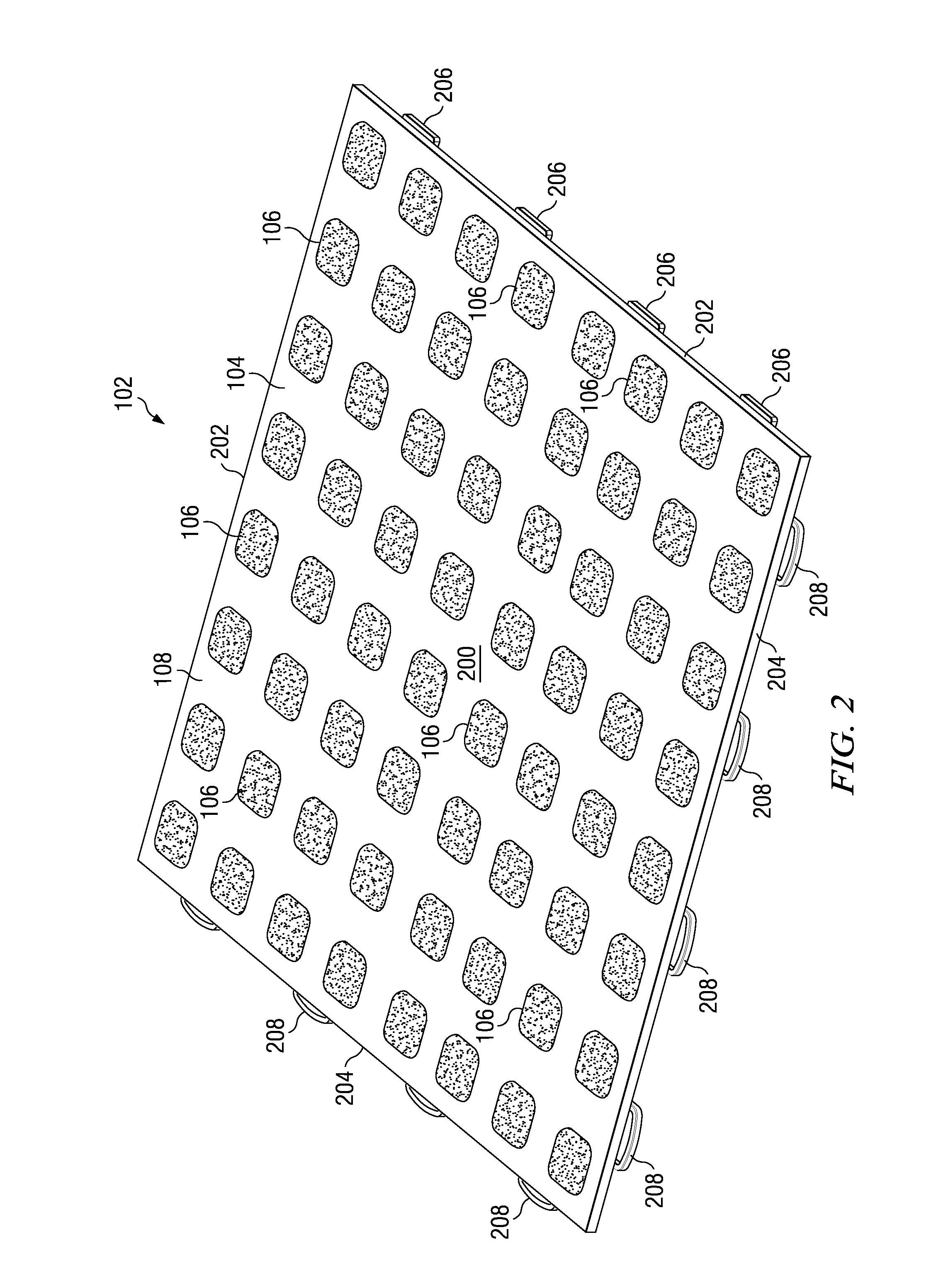
The invention provides a modular floor tile that can be easily molded and overmolded to create a flooring surface with multiple tiles. The tiles have a unique design with a raised feature on the upper surface and a vent hole to prevent any voids or flash during the molding process. The method also allows for the simultaneous molding of different features on the tiles, such as support member skins and nonslip pads. The technical effects of the invention include improved manufacturing efficiency, reduced costs, and improved quality of the molded floor tiles.

Problems solved by technology

But manufacturing an injection-molded plastic tile that has two or more perceptible colors per tile is more difficult and to date no such tile has been provided that has proven to be acceptable to the consumer.
But it is believed that the separate molding of these inserts, flash removal from them and physical insertion of them into respective receiving holes in the plastic tile substrate is time-consumptive and greatly increases the cost of manufacture of the resultant tile.

Method used


Image

  • Floor tile with overmold crush pads
  • Floor tile with overmold crush pads
  • Floor tile with overmold crush pads

Examples


third embodiment

[0043]The differences between the first and second polymer compounds can include color and / or hardness. In one embodiment the second polymer compound, once solidified, is softer or less rigid than the first (once solidified), and has a higher coefficient of friction with respect to most objects than does the first. In another embodiment the hardness of the first and second compounds (once solidified) is about the same, but the colors are distinctly different. In a third embodiment, the hardness (once solidified) of the second compound is greater than that of the first. In a preferred embodiment, the second polymer compound can be selected from the group consisting of styrene ethylene butylene styrene based thermoplastic elastomer (SEBS TPE), other TPEs, soft TPU, or soft PVC. Polypropylene as the principal polymer in the first compound, and SEBS TPE as the principal polymer in the second polymer, are particularly preferred and have demonstrated good adherence to each other.

[0044]One...

fifth embodiment

[0078]FIGS. 21 and 22 show the invention in which modifications to the latch and loop structure have been made. In this embodiment an undercut or trench 2100 is made behind (laterally inwardly from) the lateral edge 204, but laterally outwardly from the rib segment 1022, to approximately fifty percent of the thickness of web 200. The undercut 2100 extends in parallel to edge 204 for the interior length of the wall segment 1022 between its attachment points (1024, 1026; FIG. 10) with female loop 208. The undercut 2100 leaves a downwardly depending flange 2102 which, when surface 2104 of outer wall 2106 slides vertically downward along surface 204, will flex inward (to the left in this picture) in approximately the direction of arrow 2108. The depth of the undercut 2100 is chosen to get a sufficient flexure of the flange 2102 upon snapping the tiles together, and may be more or less deep than shown depending on the flexural modulus of the polymer used to mold tile body 104. Flexing fl...


PUM

PropertyMeasurementUnit
lengthaaaaaaaaaa
lengthaaaaaaaaaa
lengthaaaaaaaaaa

Abstract

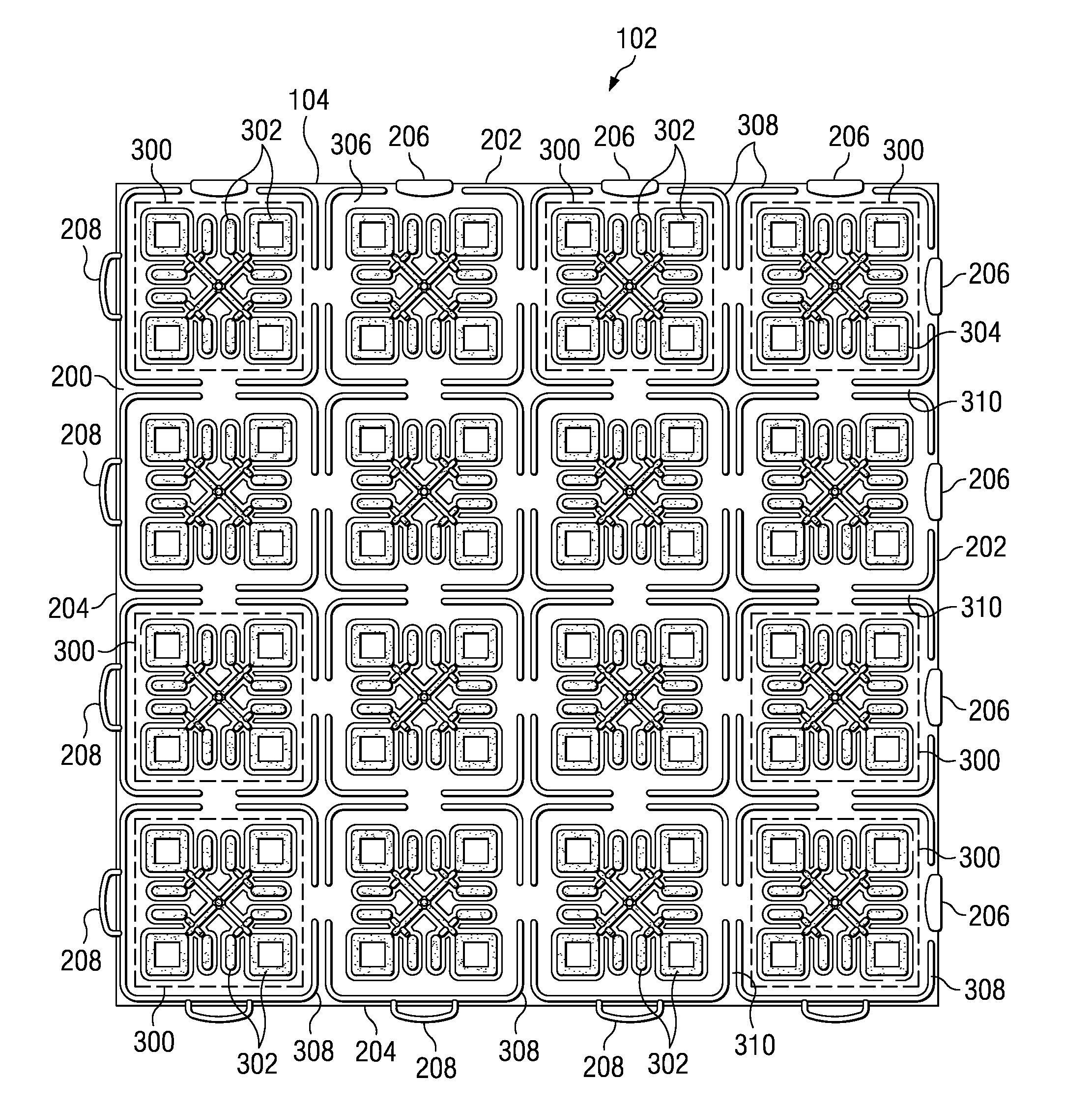
A modular plastic floor tile has a body of a first polymer compound and at least one skin overmolded onto the support member core from a second polymer compound. The compounds may be different from each other in hardness and / or color. Crush pads are formed from the first polymer and are disposed to be below the general lower surface of the tile. The crush pads provide a tight overmold shutoff and prevent flashing of the second polymer compound when the support member is formed.

Description

RELATED APPLICATIONS[0001]This application is a continuation in part of copending U.S. patent application Ser. No. 12 / 609,959 filed Oct. 30, 2009, and further is a continuation in part of copending International Patent Application No. PCT / US10 / 54515 filed Oct. 28, 2010, which in turn is a continuation in part of pending U.S. patent application Ser. No. 12 / 609,959 filed Oct. 30, 2009. The present application is further a division of pending U.S. patent application Ser. No. 13 / 217,556 filed Aug. 25, 2011. All of the foregoing applications are owned by a common assignee. The specifications and drawings of each of them are fully incorporated by reference herein.BACKGROUND OF THE INVENTION[0002]Conventional modular injection-molded tiles are known in the art for laying across upper surfaces of garage floors, sports surfaces, outdoor surfaces and other substrates. These tiles typically are twelve to thirteen inches square and can be manually assembled and disassembled. A common feature of...

Claims


Application Information

Patent Timeline
Patent Type & Authority Applications(United States)
IPC IPC(8): E04F15/02
CPCE01C5/226E01C13/045E01C2201/12E01C2201/16Y10T428/24521E04F15/02172E04F15/105E04F2201/0146E04F2201/021E04F15/02161E04F15/02194
Inventor MASANEK, JR., FREDERICK W.MALEWIG, THOMASIVERSON, DAVID S.THOM, ALLAN R.
Owner MACNEIL IP
Learn More