Battery pack

Active Publication Date: 2013-04-18
GS YUASA INT LTD
View PDF7 Cites 28 Cited by
  • Summary
  • Abstract
  • Description
  • Claims
  • Application Information

AI Technical Summary

Benefits of technology

[0005]It is an object of the present invention to easily prepare insulating members even if the number of single ce

Problems solved by technology

In such battery pack, newly designing and producing the insulating member every time when the number of single cells is changed causes complexity of desi

Method used


Image

  • Battery pack
  • Battery pack
  • Battery pack

Examples


Embodiment Construction

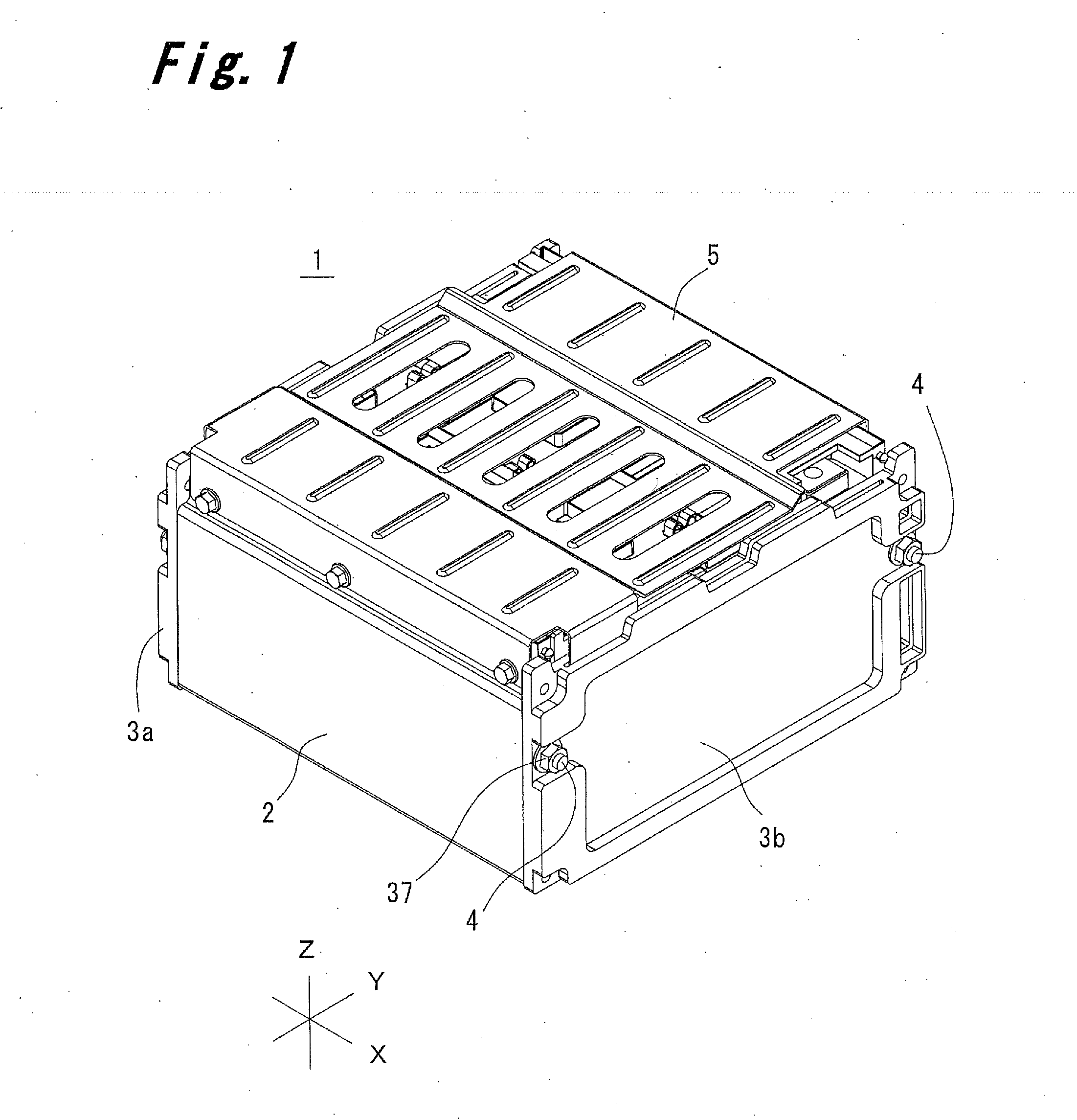
[0033]An embodiment of the present invention will be described below with reference to the accompanying drawings. Herein, for convenience sake of description, X and Y axes which intersect with each other at right angles on a horizontal plane and a Z axis which intersects with the X and Y axes at right angles are set as shown in FIG. 1. Directions which are parallel to the X, Y, and Z axes are respectively referred to as an X direction, a Y direction, and a Z direction, respectively.

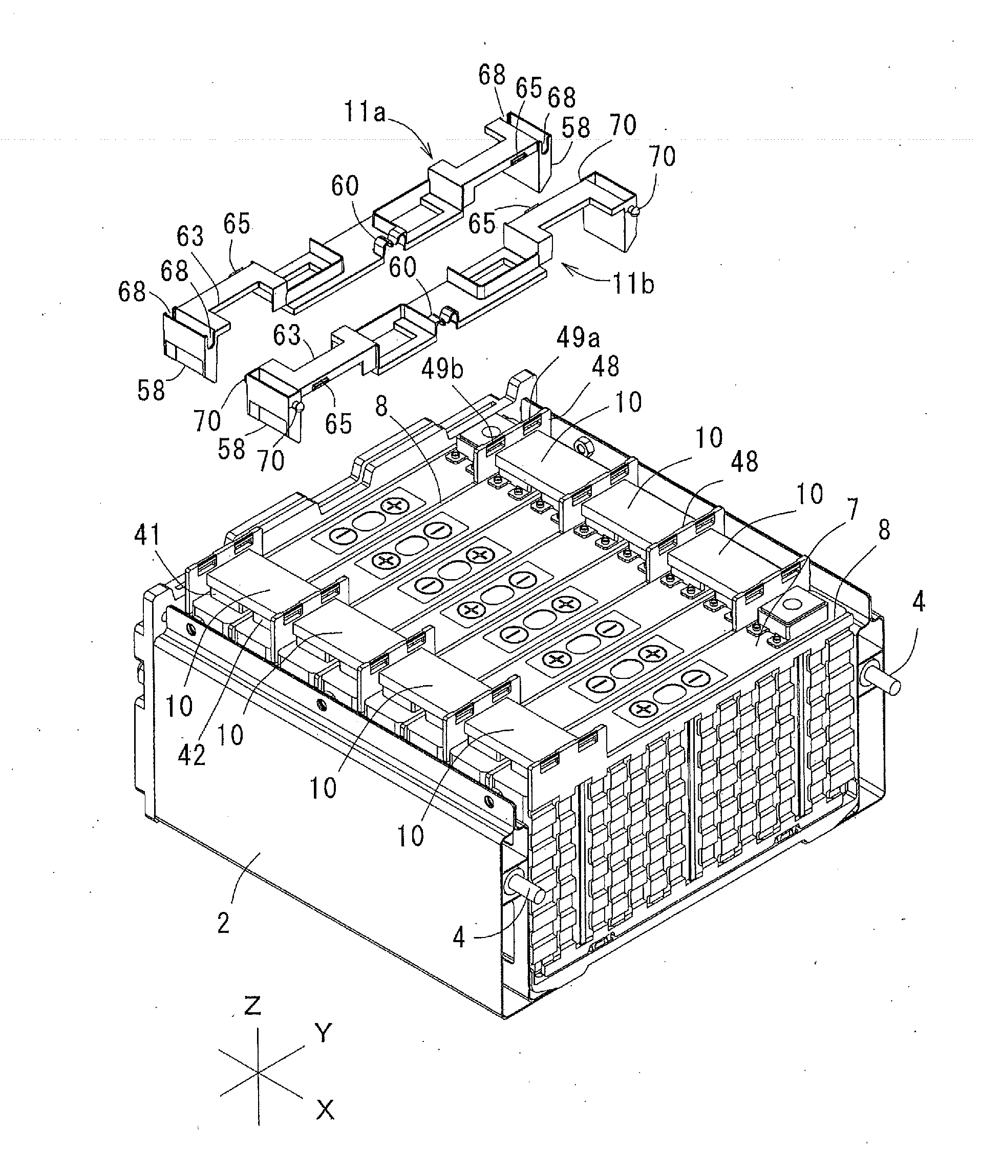
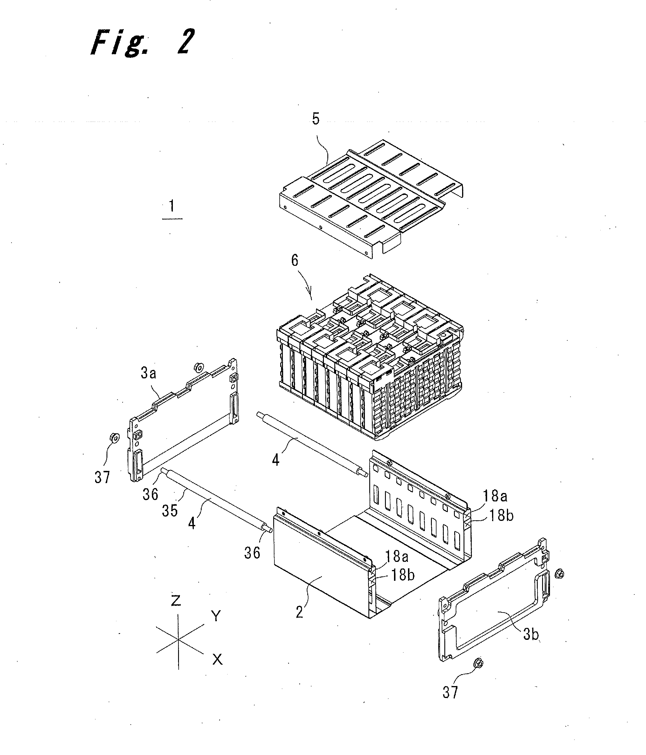
[0034]FIG. 1 shows a battery pack 1 according to the embodiment of the present invention. As shown in FIG. 2, the battery pack 1 mainly includes a stack case 2, end plates 3a and 3b, assembling shafts 4, a stack outer cover 5, and a battery pack assembly 6.

[0035]As shown in FIG. 4, the stack case 2 is formed from steel plate. The stack case 2 includes a rectangular bottom plate 12 extending in the X and Y directions, and a left wall portion 13a and a right wall portion 13b formed upright, in the Z directi...


PUM


Abstract

A battery pack includes a stack case, spacers, and inner cover members as insulating members. The stack case accommodates a plurality of single cells arranged in line. Each of the spacers is disposed between adjacent single cells. The inner cover member is provided for each of the single cells, and is disposed on a surface of the single cell where terminals are provided. The inner cover member includes a base portion opposed to a surface of the single cell between terminals and terminal insulating portions provided on both ends of the base portion and covering the terminals. The inner cover member is attached to the spacer.

Description

[0001]This application claims priority from Japanese Patent Applications Nos. 2011-214403 and 2012-213023, the disclosures of which are incorporated herein by reference in their entireties.BACKGROUND OF THE INVENTION[0002]The present invention relates to a battery pack having a plurality of single cells combined together, more particularly, to a structure of an insulating member arranged between terminals of adjacent single cells.Description of Related Art[0003]A battery pack having a plurality of single cells combined together as disclosed in JP 2010-272251 A and JP 2011-76967 A requires insulating members for preventing short circuit between the single cell and a metal case for accommodating the battery pack, as well as short circuit between the single cells.[0004]The battery pack includes a large number of single cells, but the number of single cells is changed depending on the intended use. In such battery pack, newly designing and producing the insulating member every time when...

Claims


Application Information

Patent Timeline
IPC IPC(8): H01M2/10H01M50/209H01M50/276H01M50/289
CPCH01M10/5004H01M10/5061H01M10/5032H01M10/5059H01M2/1016H01M2/1072H01M10/5044H01M10/647H01M10/6557H01M10/655H01M10/613H01M10/656Y02E60/10H01M50/507H01M50/588H01M50/291H01M50/233H01M50/593H01M50/273H01M50/209H01M50/276H01M50/289H01M50/20H01M50/543H01M50/40H01M10/637
Inventor YOSHIOKA, TOSHIKIKUSUNOKI, TOSHIKIMASUDA, YOSHIHIRO
Owner GS YUASA INT LTD
Why Eureka
Try Eureka