

Antenna selection based on orientation, and related apparatuses, antenna units, methods, and distributed antenna systems
a technology of orientation and selection, applied in the field of remote antennas or antenna arrays, can solve problems such as reducing the quality of communications link between raus and client devices, and achieve the effect of reducing the quality of communications link
- Summary
- Abstract
- Description
- Claims
- Application Information
AI Technical Summary
Benefits of technology
Problems solved by technology
Method used
Image

Examples
Embodiment Construction
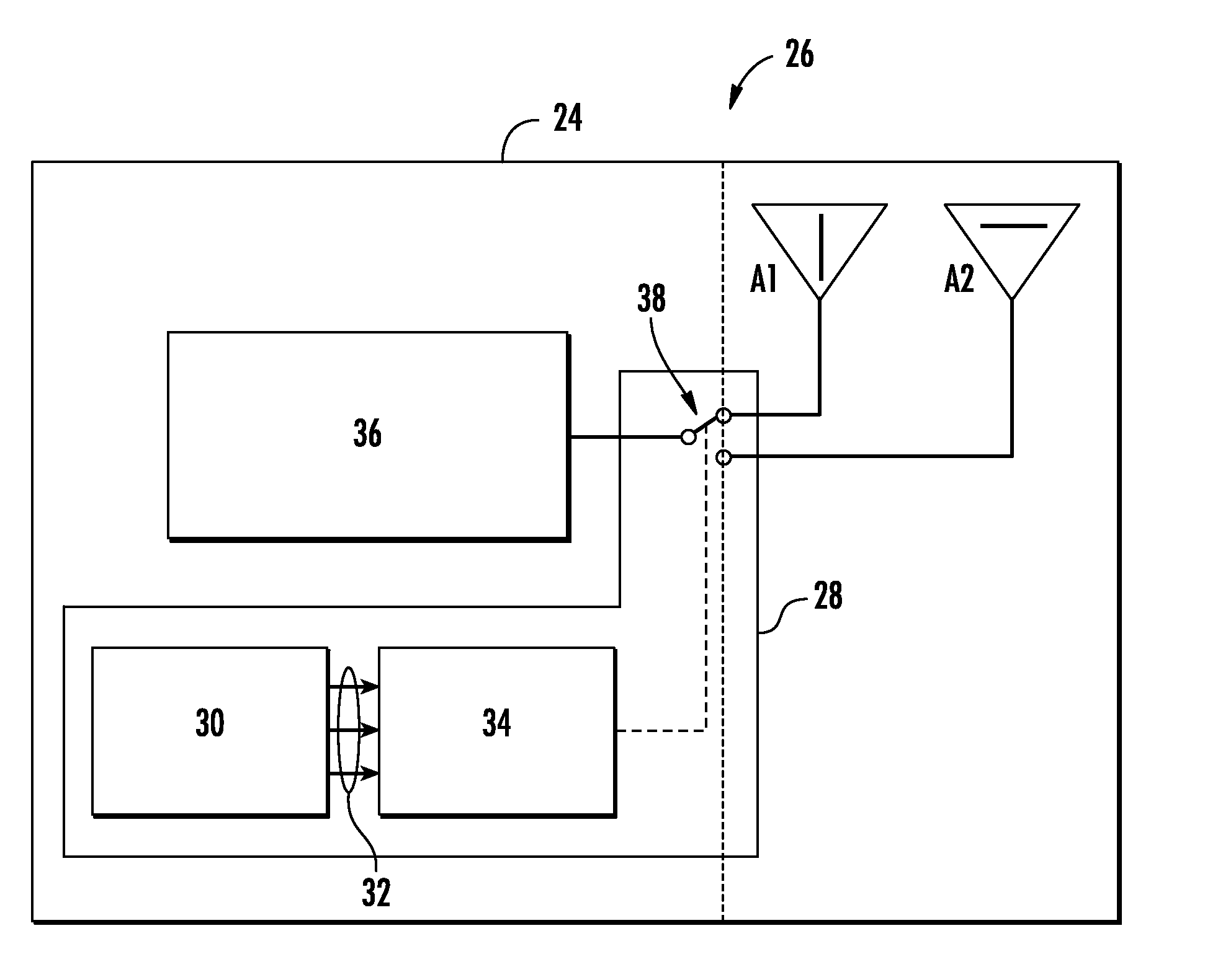
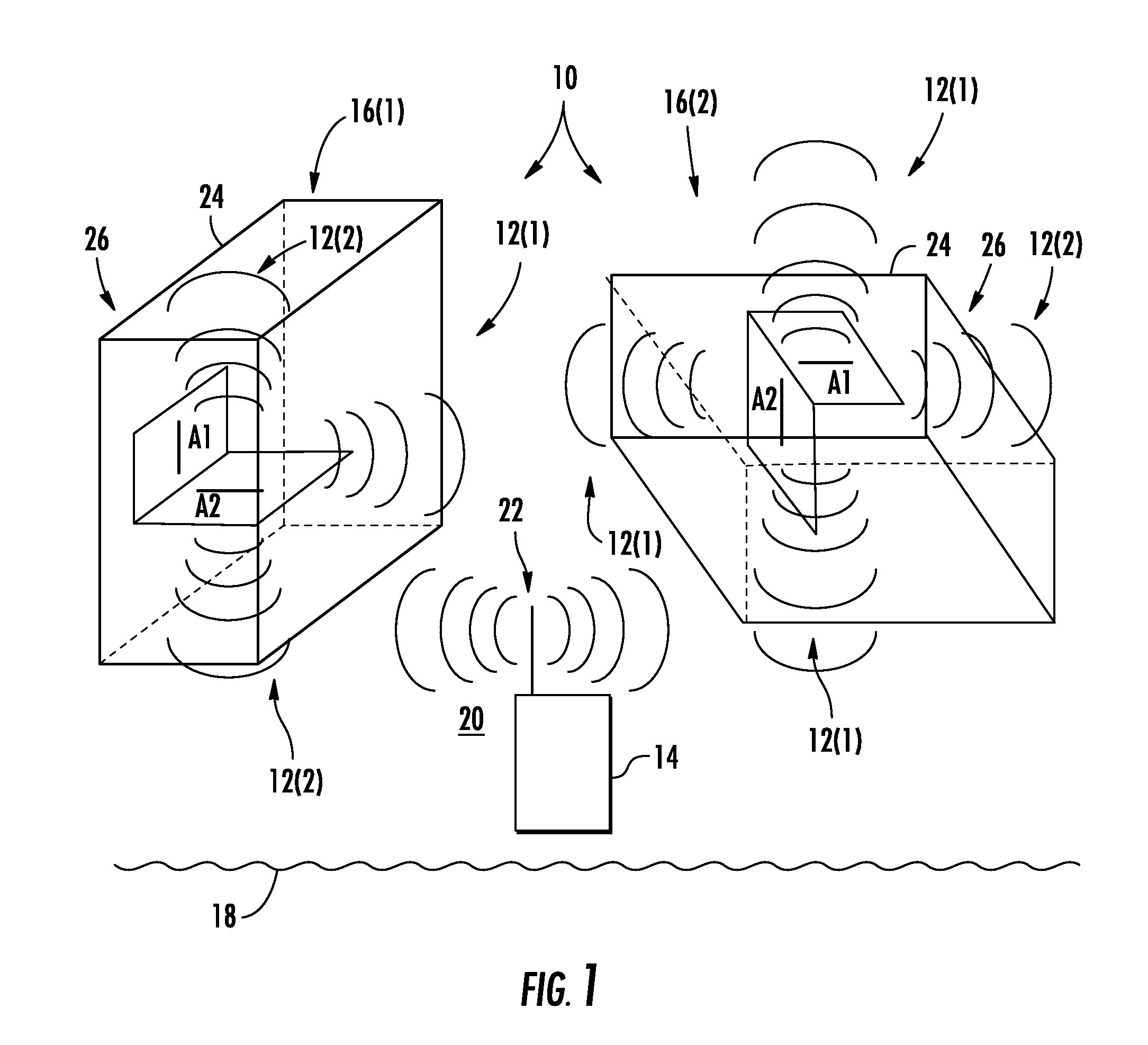
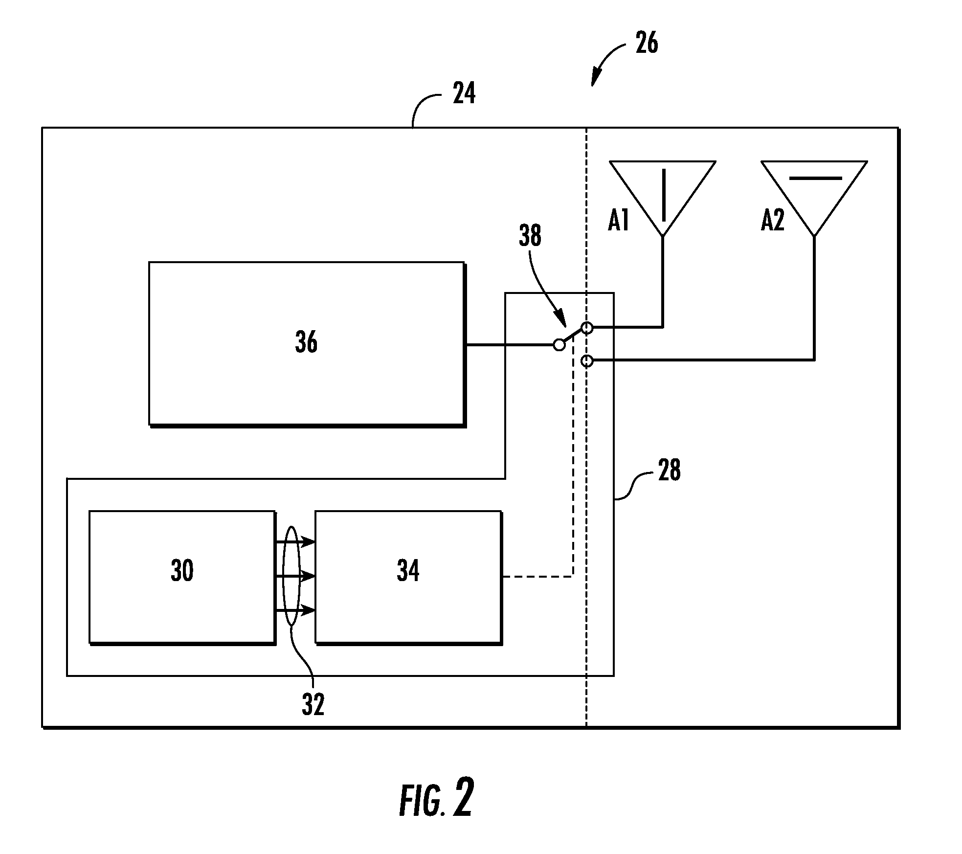
[0008]Embodiments disclosed herein include antenna apparatuses and related antenna units that include antenna selection based on orientation. Related methods and distributed antenna systems are also disclosed. Antenna selection is provided between two or more antennas disposed in different polarization orientations according to the orientation of the apparatus or antenna unit in which the antennas are included. The polarization of an antenna is defined as the orientation of the electric field (E-field) of radio frequency (RF) waves emitted by the antenna with respect to a reference antenna of a wireless client device. For example, it may be typical for a wireless client device antenna to be oriented perpendicular referring to the Earth (also referred to herein as “the ground”) to provide a vertical polarization with respect to the ground. Thus, in certain embodiments disclosed herein, the antenna(s) most closely oriented perpendicular to the ground is automatically selected for use ...
PUM
 Abstract
Description
Claims
Application Information