Dual Fuel Injector With Hydraulic Lock Seal And Liquid Leak Purge Strategy

a dual fueling system and hydraulic lock technology, applied in liquid fuel feeders, machines/engines, mechanical instruments, etc., can solve problems such as failure to anticipate problems or teach solutions to potential operational modes of engines equipped with dual fueling systems that utilize gaseous and liquid fuels, and difficulty in achieving successful ignition of gaseous fuels,

Inactive Publication Date: 2013-04-25
CATERPILLAR INC
View PDF11 Cites 45 Cited by
  • Summary
  • Abstract
  • Description
  • Claims
  • Application Information

AI Technical Summary

Benefits of technology

[0007]In still another aspect, a method of operating a dual fuel compression ignition engine includes injecting both gaseous and liquid fuels into an engine cylinder in each engine cycle from a gaseous nozzle outlet set and a liquid nozzle outlet set, respectively, of a dual fuel injector when a dual fuel system is in a dual fuel mode. Only liquid fuel is injected into the engine cylinder in each engine cycle from the liquid nozzle outlet set of the dual fue

Problems solved by technology

However, gaseous fuels are well known for the difficulty in attaining successful ignition.
While this reference may teach an effective strategy for inhibiting leakage of gaseous fuel into the liquid fuel within the dual fuel injector, it fails to anticipate problems or teach solutions to potential

Method used


Image

  • Dual Fuel Injector With Hydraulic Lock Seal And Liquid Leak Purge Strategy
  • Dual Fuel Injector With Hydraulic Lock Seal And Liquid Leak Purge Strategy
  • Dual Fuel Injector With Hydraulic Lock Seal And Liquid Leak Purge Strategy

Examples


Embodiment Construction

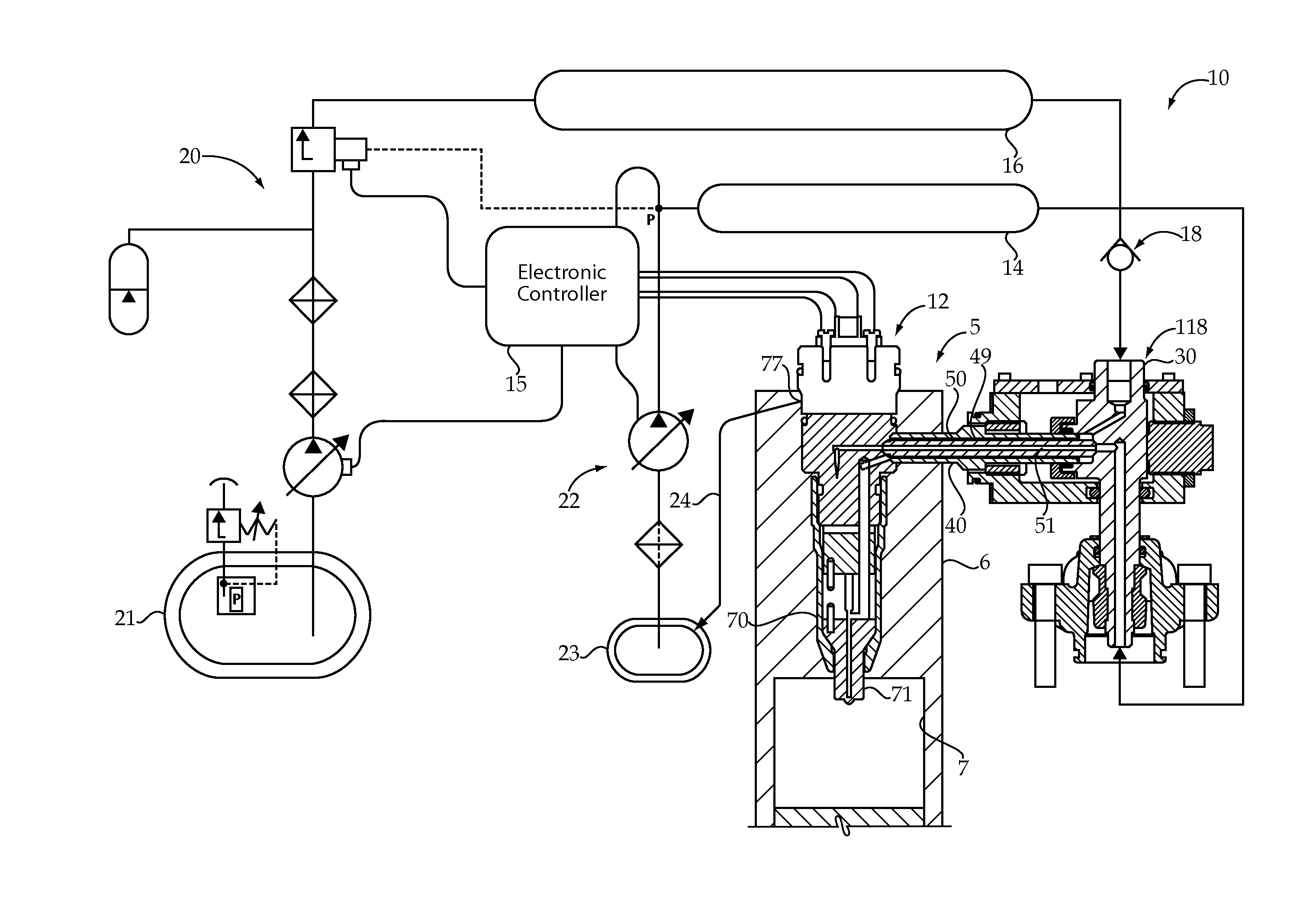
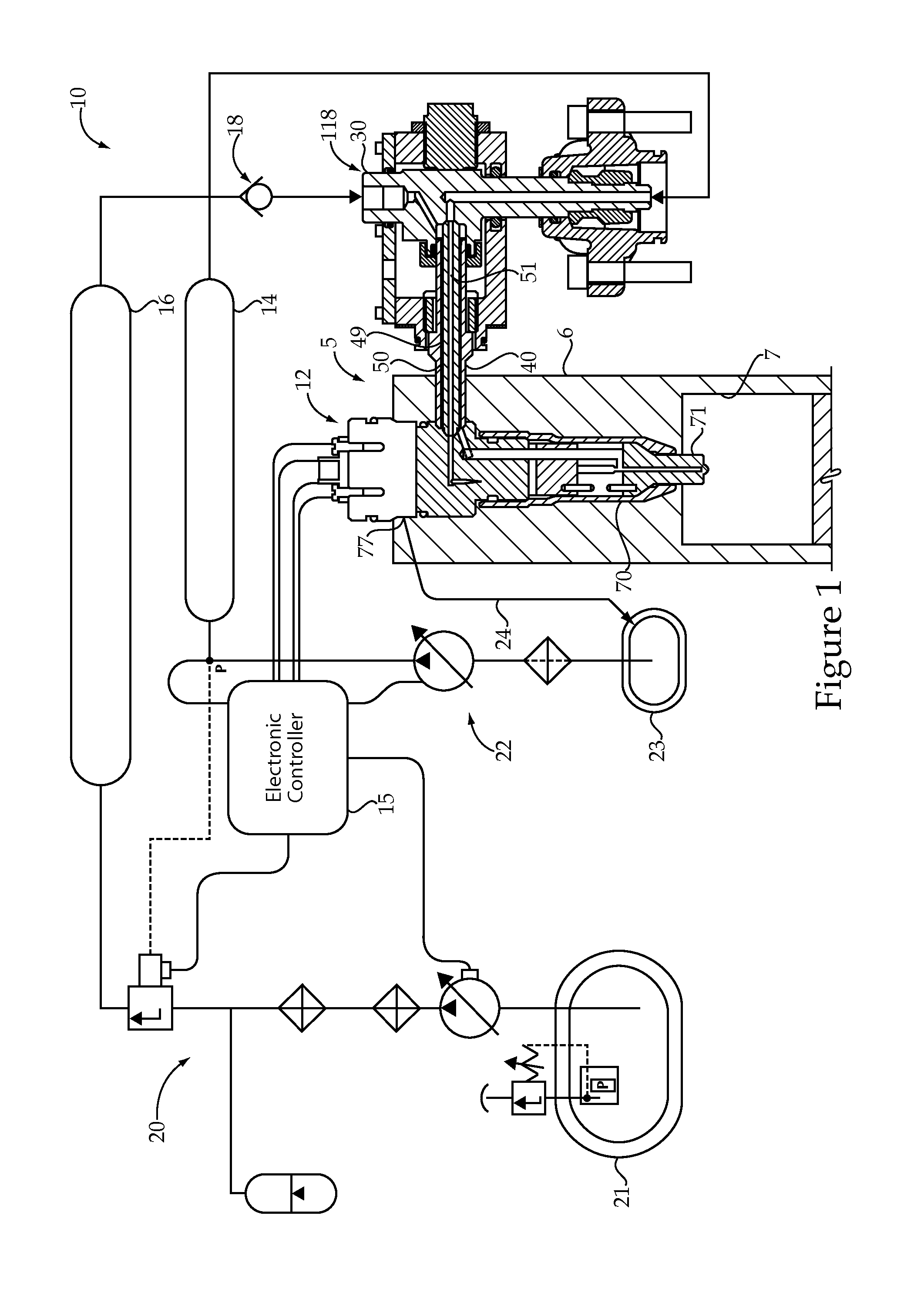
[0020]Referring to FIG. 1, an engine 5 according to the present disclosure utilizes a dual fuel common rail system 10. Engine 5 includes an engine housing 6 that defines a plurality of cylinders 7, only one of which is shown. The dual fuel system 10 includes a plurality of dual fuel injectors 12 (only one shown) that each include an injector body 70 with a tip component 71 positioned for direct injection of gaseous fuel and / or liquid fuel into one of the engine cylinders 7. The dual fuel system 10 includes a plurality of outer tubes 50 and inner tubes 40 that each extend into engine housing 6 between a quill 30 and one of the fuel injectors 12. Each of the inner tubes 50 is compressed between a conical seat on an associated quill 30 and a conical seat on one of the fuel injectors 12. Thus, each engine cylinder 7 has one associated fuel injector 12, one outer tube 40, one inner tube 50 and one quill 30. The dual fuel system 10 includes a source of gaseous fuel in the form of a gaseou...


PUM


Abstract

A dual fuel system includes a dual fuel injector that has disposed therein a gaseous nozzle chamber fluidly connected to a gaseous fuel inlet, and a liquid nozzle chamber fluidly connected to the liquid fuel inlet. The dual fuel injector also includes a hydraulic lock seal with an annular volume of liquid fuel surrounding a guide segment of a gas needle valve member for inhibiting migration of gaseous fuel into the liquid fuel. A liquid fuel common rail is fluidly connected to a liquid fuel inlet. A check valve is fluidly positioned between the gaseous fuel common rail and the gaseous nozzle chamber of the dual fuel injector for blocking liquid fuel leaked into a gaseous nozzle chamber through the hydraulic lock seal from entering the gaseous fuel common rail.

Description

TECHNICAL FIELD[0001]The present disclosure relates generally to dual fuel injection systems with hydraulic lock seals, and more particularly to preventing leaked liquid fuel from back flowing into a gaseous fuel common rail.BACKGROUND[0002]Gaseous fuel engines are known for their ability to burn clean relative to their compression ignition engine counterparts. However, gaseous fuels are well known for the difficulty in attaining successful ignition. Some gaseous fuel engines utilize a spark plug, whereas other engines are known for utilizing a small amount of distillate diesel fuel that is compression ignited to in turn ignite a larger charge of gaseous fuel. In these engines, the gaseous fuel may be supplied to the engine intake manifold or metered directly into individual cylinders where it is mixed with air prior to being ignited responsive to the pilot diesel injection near top dead center.[0003]U.S. Pat. No. 6,298,833 teaches a dual fuel injector with the ability to directly i...

Claims


Application Information

Patent Timeline
IPC IPC(8): F02M43/04F02M69/04
CPCF02M43/04F02M2200/44F02M21/023F02D19/10F02D19/0694Y02T10/30
Inventor KIM, HOISANSOMMARS, MARK F.STOCKNER, ALAN
Owner CATERPILLAR INC
Why Eureka
Try Eureka