
Combined mixing and discharging device

Active Publication Date: 2013-04-25
MEDMIX SWITZERLAND AG
View PDF9 Cites 12 Cited by
  • Summary
  • Abstract
  • Description
  • Claims
  • Application Information

AI Technical Summary

Benefits of technology

The patent describes a device that allows for the mixing of powdery or paste-like substances without the risk of leakage or positive pressure in the reservoir. The device includes a piston and an advancement element that can be coupled or uncoupled to allow for the mixing of components. The piston and advancement element seal the reservoir in both states, preventing any leakage or air from entering during the mixing process. The device also includes a securing element that only allows decoupling if the piston has been withdrawn from the housing up to a certain point. This ensures the safety and stability of the device during the mixing process.

Problems solved by technology

Consequently, a dangerous overpressure can arise in the first container.
However, if the first container is designed in such a manner that the region of the piston is permeable to air, it is not possible to suck the liquid into the first container by withdrawing the piston of the first container, because it is not possible to generate a vacuum in the first container.
It is thus not possible with the use of one and the same device to optionally place the liquid into the second container by sliding in the piston of the second container or by withdrawing the first piston; instead, because of the design of the discharging device the user is restricted to one of these two options.
Furthermore, it is disadvantageous if air can enter through the region of the piston into the first container, because it is possible that as a result of this the chemical characteristics of the product received in the first container are altered during storage.
While in such a design it is possible, without further ado, to suck up a liquid into the container by retracting the piston, in those cases where the user would like to fill liquid into the container by injecting the liquid into said container by means of a separate syringe, again, dangerous overpressure can result in the container.
Moreover, when the substances received in the housing are mixed by means of the mixing device, in such a device negative pressure or positive pressure can result.
During subsequent opening of the outlet opening, any remaining positive pressure or negative pressure in the container can result in part of the product being ejected from the container or in air being sucked in.
This is problematic, in particular in the case of toxic products, highly corrosive products or in products requiring precise dosing.

Method used


Image

  • Combined mixing and discharging device
  • Combined mixing and discharging device
  • Combined mixing and discharging device

Examples


Embodiment Construction

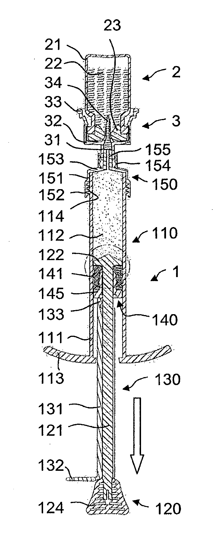
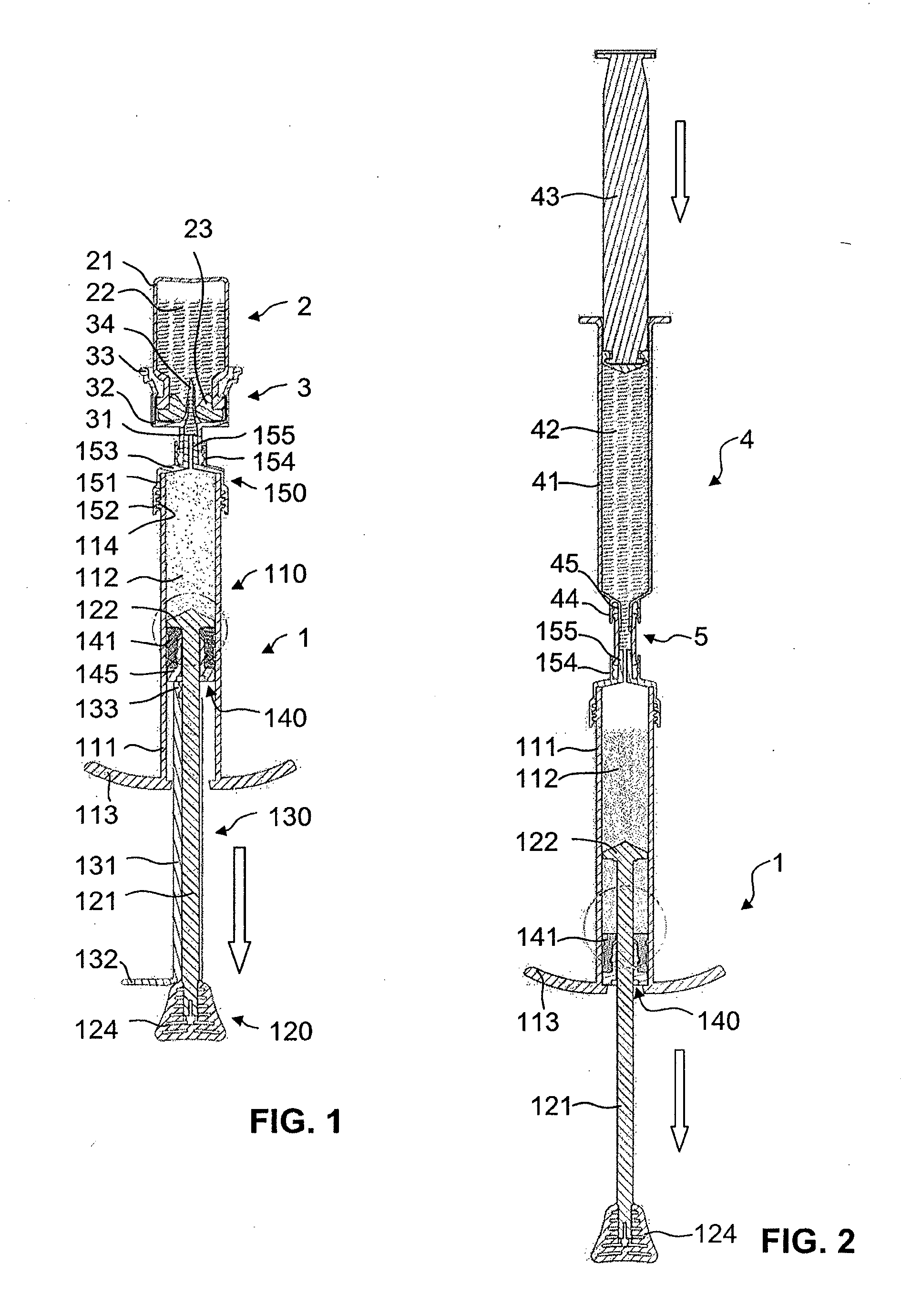
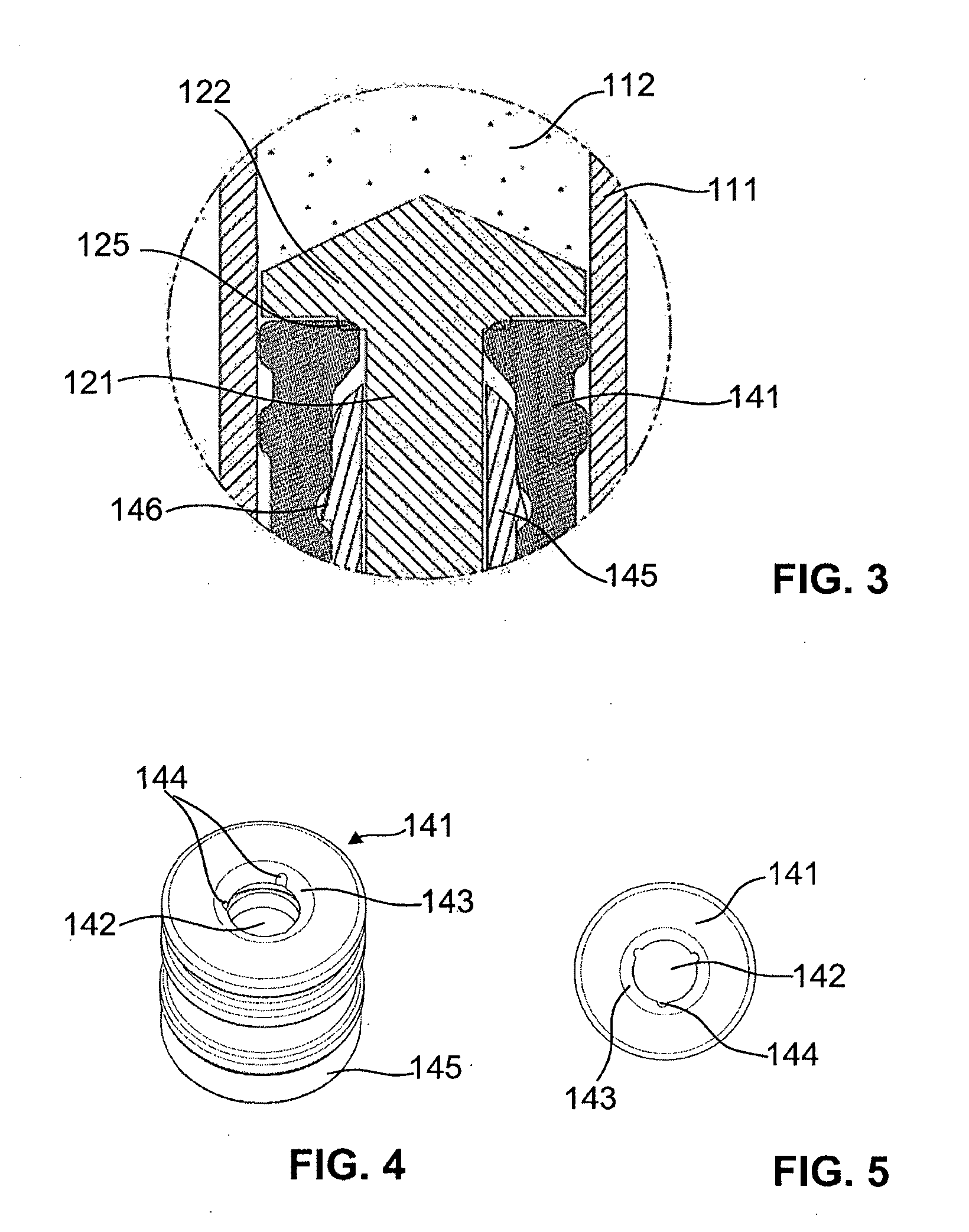
[0044]FIGS. 1 to 11 show a discharging device 1 according to the invention according to a preferred embodiment. The discharging device 1 of this embodiment is a syringe which is used, for example, for mixing and administering a medicament or for mixing and discharging an adhesive or a bone cement. The discharging device 1 comprises a housing 110 in which an advancement element 120 is slidably arranged along an axial longitudinal direction. In this arrangement the advancement element 120 is slid from a proximal end into the housing 110. In the housing 110, furthermore, a piston 140 is arranged that is slidable in the longitudinal direction relative to the housing 110 and to the advancement element 120. In the present embodiment, in addition, a securing element 130 can be affixed to the advancement element 120, and at the distal end a connection attachment 150 is screwed onto the housing 110.

[0045]The housing 110, which can also be referred to as a syringe body, comprises a circumfere...


PUM


Abstract

The invention provides a discharging device (1) which is intended for mixing and discharging a product and has a housing (110) with a reservoir (112). An advancement element (120), which can be displaced in the housing (110), has a mixing element (112) for mixing the product. A piston (140) can be displaced in the longitudinal direction relative to the housing (110), in order for the product to be ejected out of the reservoir (112) through an outlet opening. The piston (140) here has an uncoupled state, in which it can be displaced in the longitudinal direction relative to the advancement element (120), and a state in which it is coupled to the advancement element (120), and in which it can be displaced in the longitudinal direction relative to the housing (110) by means of the advancement element (120). In the coupled state, the piston (140), together with the advancement element (120), seals the reservoir (112) in an airtight manner and, in the uncoupled state, the piston (140) and / or the advancement element (120) free / frees at least one proximal venting opening (144) in the outward direction.

Description

TECHNICAL FIELD[0001]The present invention relates to a discharging device for mixing and discharging a product. The discharging device comprises a housing, a piston that can be displaced therein, and an advancement element that comprises a mixing element. Such a discharging device can, for example, be used to store a first component, to receive a second component immediately prior to application, to mix said second component with the first component, and to subsequently discharge or apply the mixed product.PRIOR ART[0002]Discharging devices in the form of syringes have been generally known for a long time. A commercially available syringe comprises a housing with a distal outlet opening and an advancement element that can be slid into the housing from a proximal end. The advancement element comprises a piston rod with a piston affixed distally thereto, which piston is sealingly displaceable in the interior of the syringe body. In order to receive a liquid in the syringe, by means o...

Claims


Application Information

Patent Timeline
IPC IPC(8): B67D7/70B67D7/60
CPCA61J1/2096A61J2001/201A61J2001/2055A61M5/1782A61M5/31596A61M2005/3123B01F13/00B01F11/0071B01F13/002B01F13/0023B01F15/00506B01F11/0082A61M2005/31508A61J1/201A61J1/2055B01F31/65B01F31/441B01F33/00B01F33/50112B01F33/5011B01F35/3202A61M2005/3151
Inventor GRETER, ANDY
Owner MEDMIX SWITZERLAND AG
Learn More