Method and apparatus for mounting conductive balls

a technology of conductive balls and mounting methods, which is applied in the direction of soldering apparatus, manufacturing tools, non-printed masks, etc., can solve the problems of long time period needed for the mounting process, the speed of the ball cup cannot be increased to high speed, and the conductive balls leak from the gap between the ball cup and the arraying mask, so as to increase the speed of the ball suction body and the ball cup. , the effect of increasing the productivity

Active Publication Date: 2013-04-25
SHIBUYA IND CO LTD
View PDF2 Cites 1 Cited by
  • Summary
  • Abstract
  • Description
  • Claims
  • Application Information

AI Technical Summary

Benefits of technology

[0008]An object of the invention is to prevent conductive balls from being caught between the ball cup or ball suction body and the arraying mask when the ball cup or ball suction body is moving by causing conductive balls being sucked to the ball suction body which lies above the arraying mask when conductive balls are caused to fall into the through holes in the arraying mask to be mounted on the mount. This allows for an increase in moving speed of the ball cup which supplies conductive balls, so as to contribute to an increase in productivity.
[0030]Since the invention is configured such that the suction state of the ball suction body is switched to ON by the vacuum switching means so that conductive balls residing below the ball suction body are sucked to the ball suction body, and thereafter, the suction state of the ball suction body is switched to OFF so as to allow the conductive balls held sucked to the ball suction body to fall so that the conductive balls so falling are mounted on the mount, it has become possible to prevent conductive balls from being caught between the ball suction body and the ball cup attached thereto and the arraying mask. As a result of this, the moving speed of the ball suction body and the ball cup can be increased, so as to realize an increase in productivity.

Problems solved by technology

In addition, as the diameters of conductive balls used get smaller, higher accuracies are required for the gap between the ball cup and the arraying mask, flatness of the arraying mask and horizontal travel of the ball cup, and with these accuracies getting lower, there has been caused a risk that conductive balls leak from the gap between the ball cup and the arraying mask.
However, since the ball cup had to be moved in such a manner that the collection conductive balls were not brought into contact therewith, the moving speed of the ball cup could not be increased to high speeds, this having led to a problem that a long period of time was necessary for the mounting process.
In addition, although it was considered that the flow speed of gas flowing in from the gap between the arraying mask and the ball cup was increased to high speeds, with the gas flow speed so increased, conductive balls were not able to be collected on the arraying mask but were caused to scatter in the gas within the ball cup, and there sometimes occurred a situation in which no conductive balls were mounted in some of the mounting locations.

Method used


Image

  • Method and apparatus for mounting conductive balls
  • Method and apparatus for mounting conductive balls
  • Method and apparatus for mounting conductive balls

Examples


first embodiment

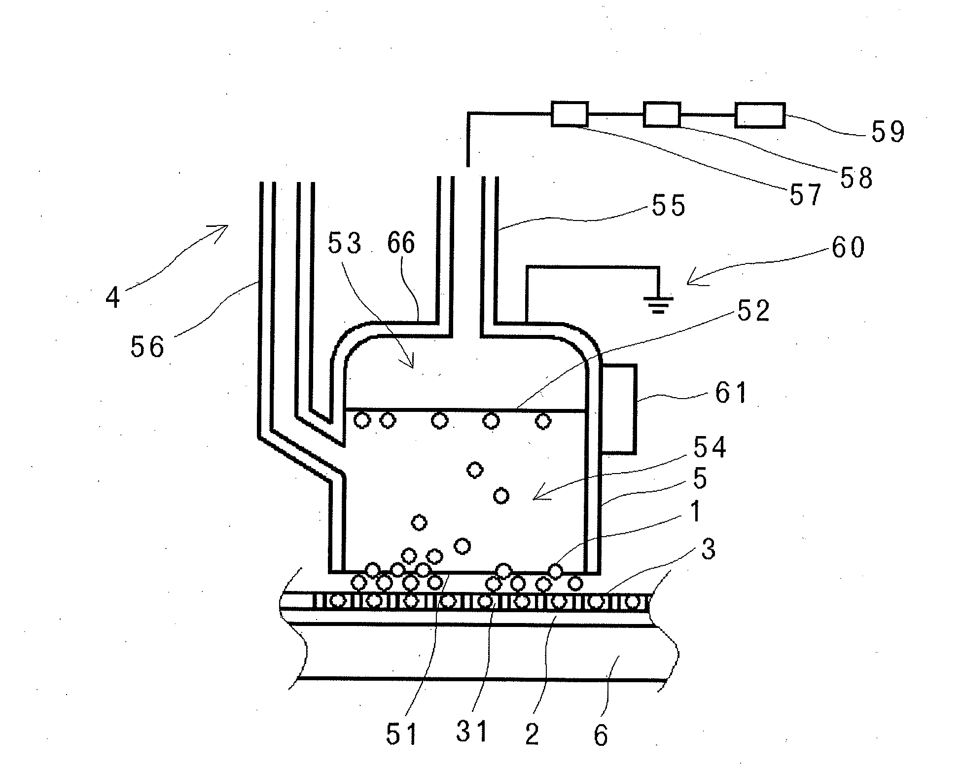
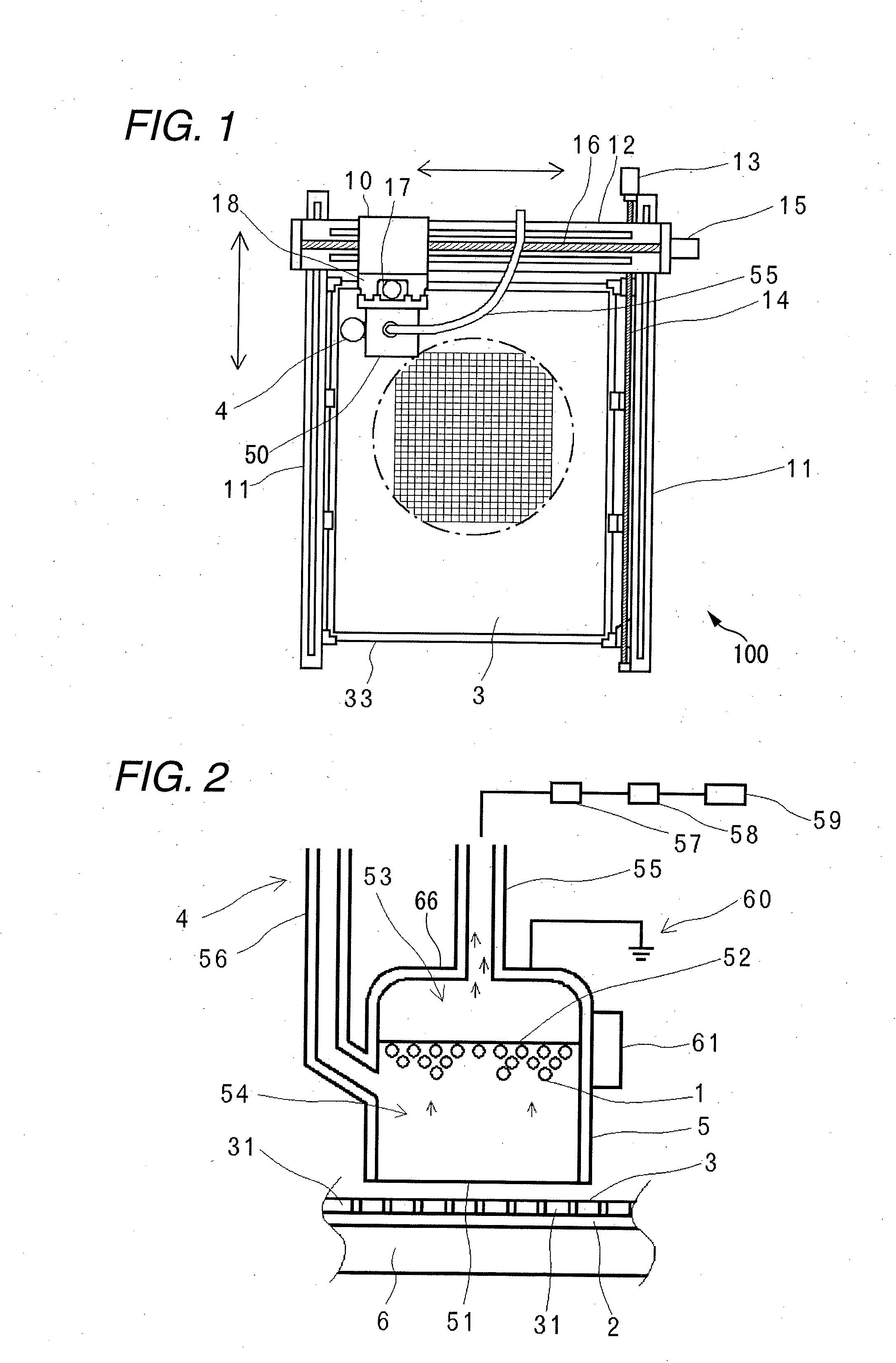
[0044]A first embodiment of the invention will explained with reference to FIG. 2. As shown in FIG. 2, the ball cup 5 has interior space and is opened in a lower end face so as to define an opening 51, and the interior space is partitioned into an upper space 53 and a lower space 54 by a ball suction element 52 as an example of a ball holding member. Thus, an upper portion of the ball cup 5 which lies further upwards than the ball suction element 52 constitutes a casing 66 for the ball suction element 52. In other words, the ball suction element 52 is provided on a lower surface of the casing 66. In the first embodiment, the ball reservoir 50 as the ball suction unit is configured by the ball cup 5, the ball suction element 52 and the casing 66. The ball suction element 52 is made of a metallic net such as a stainless mesh which does not allow for the passage of the solder balls 1 but allows for the passage of gas. In addition, in the embodiment illustrated, although the ball cup 5 ...

second embodiment

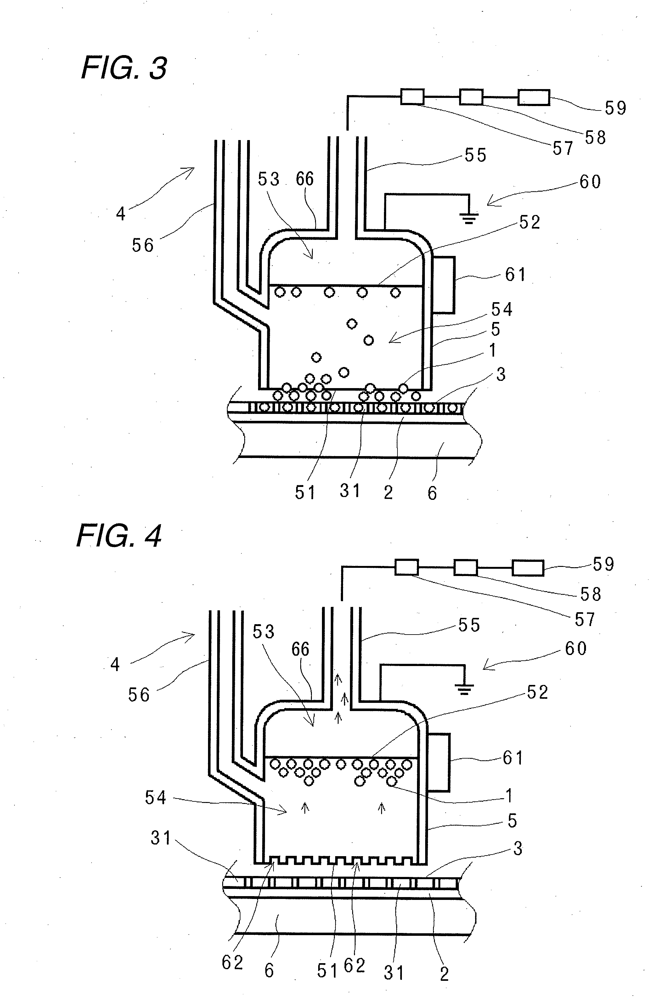
[0058]FIG. 4 shows a second embodiment of the invention. While in the first embodiment, the lower end face of the opening 51 of the ball cup 5 is formed into a planar shape which is in parallel with the ball arraying mask 3 and the ball cup 5 is disposed in such a position that the gap is formed the lower end face of the ball cup 5 and the upper surface of the ball arraying surface 3 in such a manner as to obtain the predetermined gas flow when the ball sucking operation is performed, in a second embodiment shown in FIG. 4, slits 62 are formed on a lower end face of an opening 51 of a ball cup 5 so that gas flows can be obtained. The slits 62 are preferably formed to be radiated in the opening 51 or preferably formed into spiral curves having directivity in one direction. By forming the slits 62 in this way, the flow of gas between the ball cup 5 and a ball arraying mask 3 can be controlled, thereby making it possible to prevent the floating of the ball arraying mask 3. Of course, d...

third embodiment

[0059]FIG. 5 shows a third embodiment of the invention. According to the third embodiment, in order to limit the range where the solder balls 1 drop from the ball suction element 52 down to the ball arraying mask 3, a ball guide 63, which is opened widely in an upper portion and is opened narrowly in a lower portion to match a mounting range, is provided below a ball suction element 52 of a ball cup 5.


PUM

PropertyMeasurementUnit
conductiveaaaaaaaaaa
suction stateaaaaaaaaaa
suctionaaaaaaaaaa

Abstract

A conductive ball mounting method for mounting conductive balls on a mount using an arraying mask, in which the mount includes mounting positions formed in a predetermined pattern, and the arraying mask is provided above the mount and includes through holes provided in positions corresponding to the mounting positions. The method includes providing a ball suction unit for sucking solder balls, the ball suction unit including a ball holding member capable of holding the conductive balls, sucking up the conductive balls below the ball suction unit, holding the conductive balls on a lower surface of the ball holding member while sucking up the conductive balls, and after the holding the conductive balls, falling the conductive balls held by the ball holding member to the mount.

Description

BACKGROUND OF THE INVENTION[0001]1. Field of the Invention[0002]The present invention relates to a method and apparatus for mounting conductive balls in mounting locations on amount which are formed in a predetermined pattern using an arraying mask in which through holes are provided in such a manner as to match the mounting locations.[0003]2. Description of the Related Art[0004]As a method and apparatus for mounting conductive balls in mounting locations on a mount which are formed in a predetermined pattern using an arraying mask in which through holes are provided in such a manner as to match the mounting locations, JP-A-2006-318994 discloses a method and apparatus for arraying conductive balls on amount by a ball reservoir accommodating therein a large number of conductive balls moving over an arraying jig.[0005]In the mounting approach adopted in the method and apparatus for mounting conductive balls disclosed in JP-A-2006-318994 in which conductive balls are dropped to be moun...

Claims


Application Information

Patent Timeline
Patent Type & Authority Applications(United States)
IPC IPC(8): B23K1/20
CPCH01L21/4853H05K3/3478H05K2203/041Y10T29/53191H05K2203/082B23K1/20Y10T29/49117H05K2203/0557Y10T29/49144Y10T29/49149
Inventor IKEDA, KAZUNARI
Owner SHIBUYA IND CO LTD
Why Eureka
Try Eureka