Segmented Aircraft Wing Having Solar Arrays

a solar array and aircraft technology, applied in the field of aircraft wings, can solve the problems of significantly reducing adversely affecting the integrity of the solar panel, and affecting the aerodynamic performance of the aircraft, and achieve the effect of long wingspan and low strain level

Active Publication Date: 2013-04-25
THE BOEING CO
View PDF7 Cites 38 Cited by
  • Summary
  • Abstract
  • Description
  • Claims
  • Application Information

AI Technical Summary

Benefits of technology

[0009]The disclosed embodiments provide a lightweight, flexible aircraft wing that may have a relatively long wingspan equipped with solar panels. The solar panels are substantially isolated from strains produced by wing deflection and/or changes in temperature by segmenting the wing into separate wing segments that are mounted on a wing spar by pivotal joints. This wing segmenting and wing segment mounting arrangement provides a stable load path allowing transfer of aerodynamic and inertial loads from the wing segment structure to the spar, while isolating th

Problems solved by technology

However, long, lightweight wings may be highly flexible, presenting a number of problems due to the loads imposed on the wings during flight.
Flexing of the wings during flight may cause the solar panels to experience high strains that can adversely affect the integrity of the solar panels.
These strains may also result in buckling or wrinkling of the solar panels which may trip the airflow boundary layer over the wings from laminar to turbulent

Method used


Image

  • Segmented Aircraft Wing Having Solar Arrays
  • Segmented Aircraft Wing Having Solar Arrays
  • Segmented Aircraft Wing Having Solar Arrays

Examples


Embodiment Construction

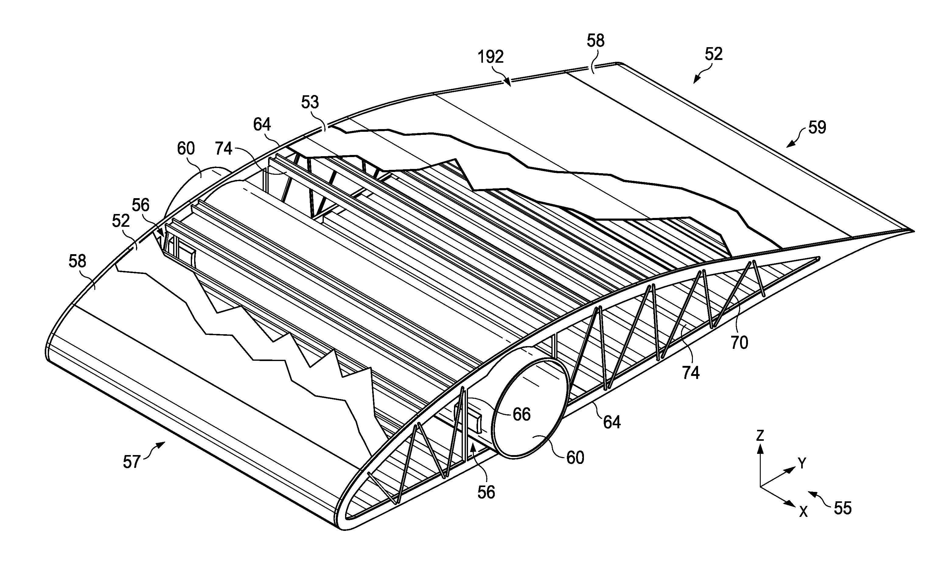
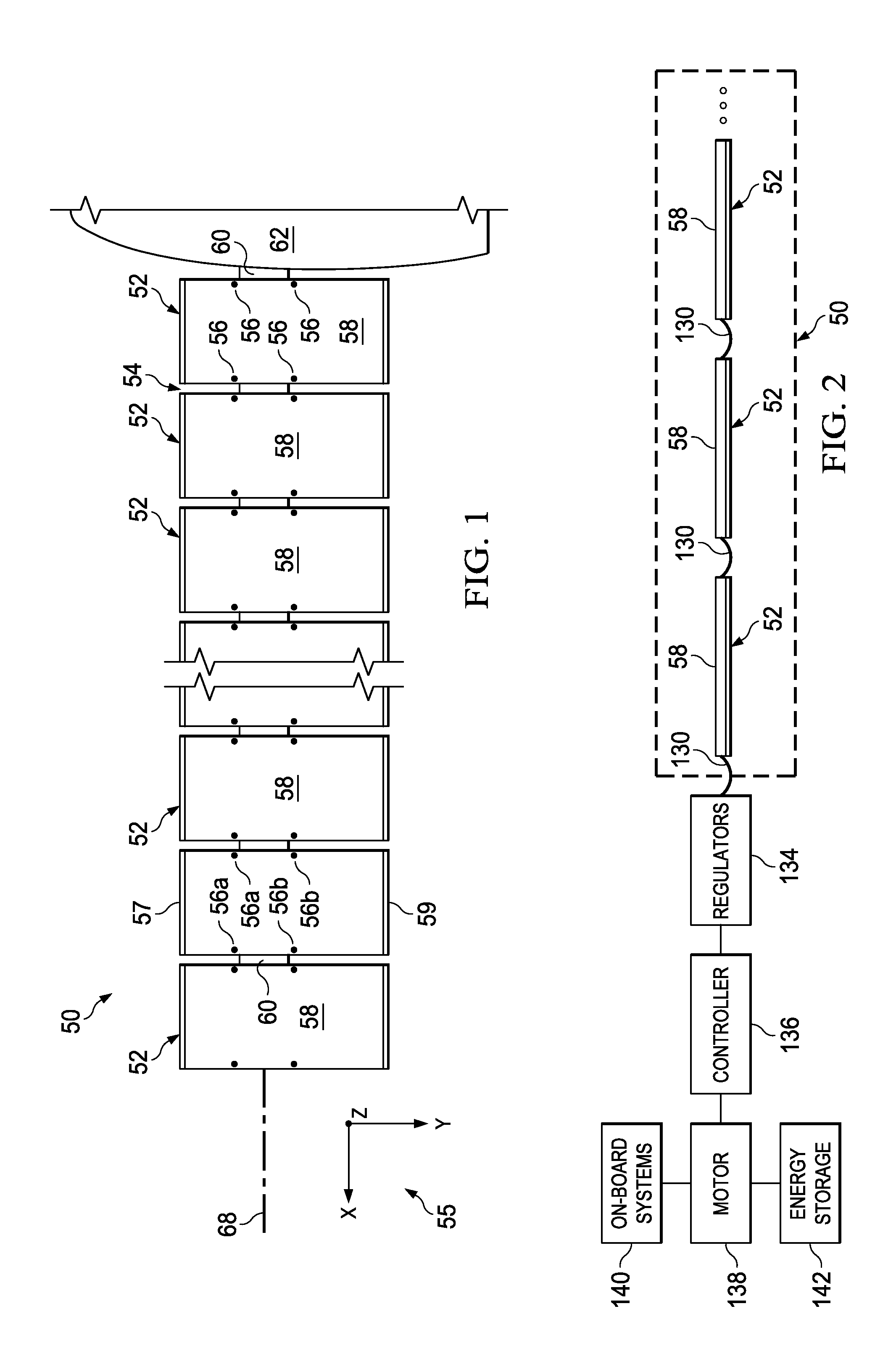
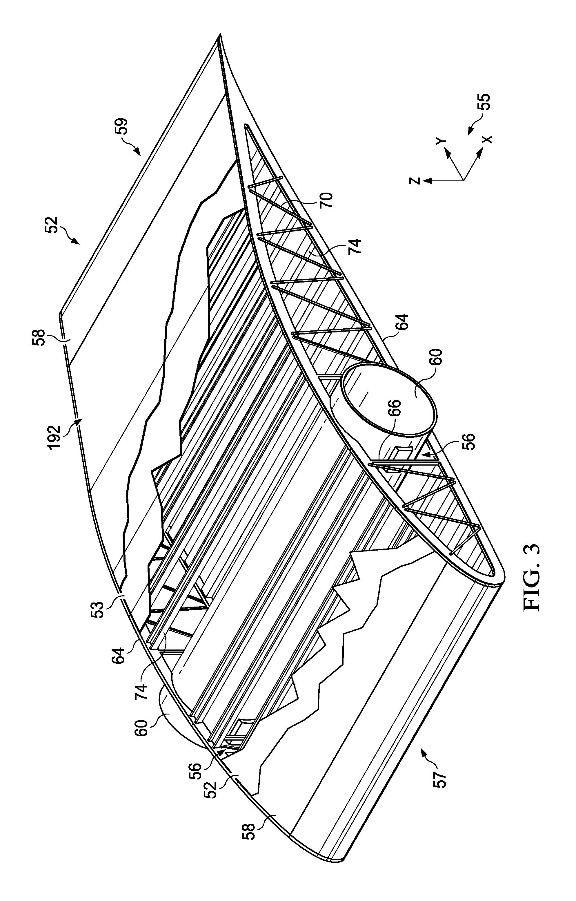
[0060]Referring first to FIG. 1, an aircraft wing 50 may be attached to a pod or fuselage 62 and is segmented into a plurality of separate wing segments 52 that are spaced apart from each other to form gaps 54 of variable width. It should be noted however, the principals of the disclosed embodiments are applicable to a wing 50 comprising a “flying wing” type aircraft that does not employ a pod or fuselage. Each of the wing segments 52 may be mounted on wing spar 60 for movement relative to the wing spar 60 when the wing spar flexes during flight. In one embodiment, each of the wing segments 52 is attached to and supported on the wing spar 60 by pivotal joints 56, however, other types of joints allowing this relative movement between the wing segments 52 and the wing spar 60 are possible. The pivotal joints 56 may comprise a pair of laterally spaced forward joints 56a, and a pair of laterally spaced aft joints 56b. In the illustrated embodiment, four pivotal joints 56 pivotally conne...


PUM

PropertyMeasurementUnit
Temperatureaaaaaaaaaa
Thicknessaaaaaaaaaa
Electrical conductivityaaaaaaaaaa

Abstract

An aircraft wing has a plurality of wing segments mounted on a wing spar by joints that allow relative movement between the spar and the wing segments. Tuning of coefficients of thermal expansion is employed to reduce induced stresses from changes in temperature.

Description

STATEMENT REGARDING FEDERALLY SPONSORED RESEARCH OR DEVELOPMENT[0001]This invention was made with U.S. Government support under Agreement No. HR0011-10-9-0010, awarded by the Defense Advanced Research Projects Agency (DARPA). The U.S. Government has certain license rights in the invention.BACKGROUND INFORMATION[0002]1. Field:[0003]This disclosure generally relates to aircraft wings, and deals more particularly with a light-weight, flexible wing having solar panels for generating electrical power.[0004]2. Background:[0005]Aircraft are known that have arrays of photovoltaic solar cells (hereinafter referred to as solar panels) on the aircraft's wings for converting solar energy into electrical power. The electrical power may be used to operate on-board aircraft systems and / or to propel the aircraft, typically using one or more electric motors and propellers. The solar panels are typically mounted on upper surfaces of the wings because this location provides favorable exposure to sunli...

Claims


Application Information

Patent Timeline
IPC IPC(8): B64C3/44B32B37/14B64C3/20B64C3/00H02N6/00
CPCB64D27/24B64D2211/00Y10T156/10B64C3/18Y02T50/62Y02T50/40Y02T50/50Y02T50/60B64C3/182B64C3/185B64C3/187B64C3/22B64C3/26
Inventor GRIP, ROBERT ERIKRAWDON, BLAINE KNIGHT
Owner THE BOEING CO
Why Eureka
Try Eureka