Valve device with a valve housing having multiple shift tongues

Active Publication Date: 2013-04-25
ZF FRIEDRICHSHAFEN AG
View PDF24 Cites 6 Cited by
  • Summary
  • Abstract
  • Description
  • Claims
  • Application Information

AI Technical Summary

Benefits of technology

[0008]The purpose of the present invention is to provide a simply designed valve device with a valve housing having a plurality of shifting tongues and a valve slide arranged to move longitudinal

Problems solved by technology

An unsymmetrical pressure field is formed, in particular, when shifting tongues of the valve housing are produced by a casting process since in that case they are not rotationally symmetrical to the required extent.
In the area of the valve slide unsymmetrical pressure fields result in radial and axial forces that act upon the valve slide and impair the functionality of the valve device.
In such pressure systems, leaks between the high-pressure area carrying the system pressure and the working pressure area are disadvantageous when the working

Method used


Image

  • Valve device with a valve housing having multiple shift tongues
  • Valve device with a valve housing having multiple shift tongues
  • Valve device with a valve housing having multiple shift tongues

Examples


Example

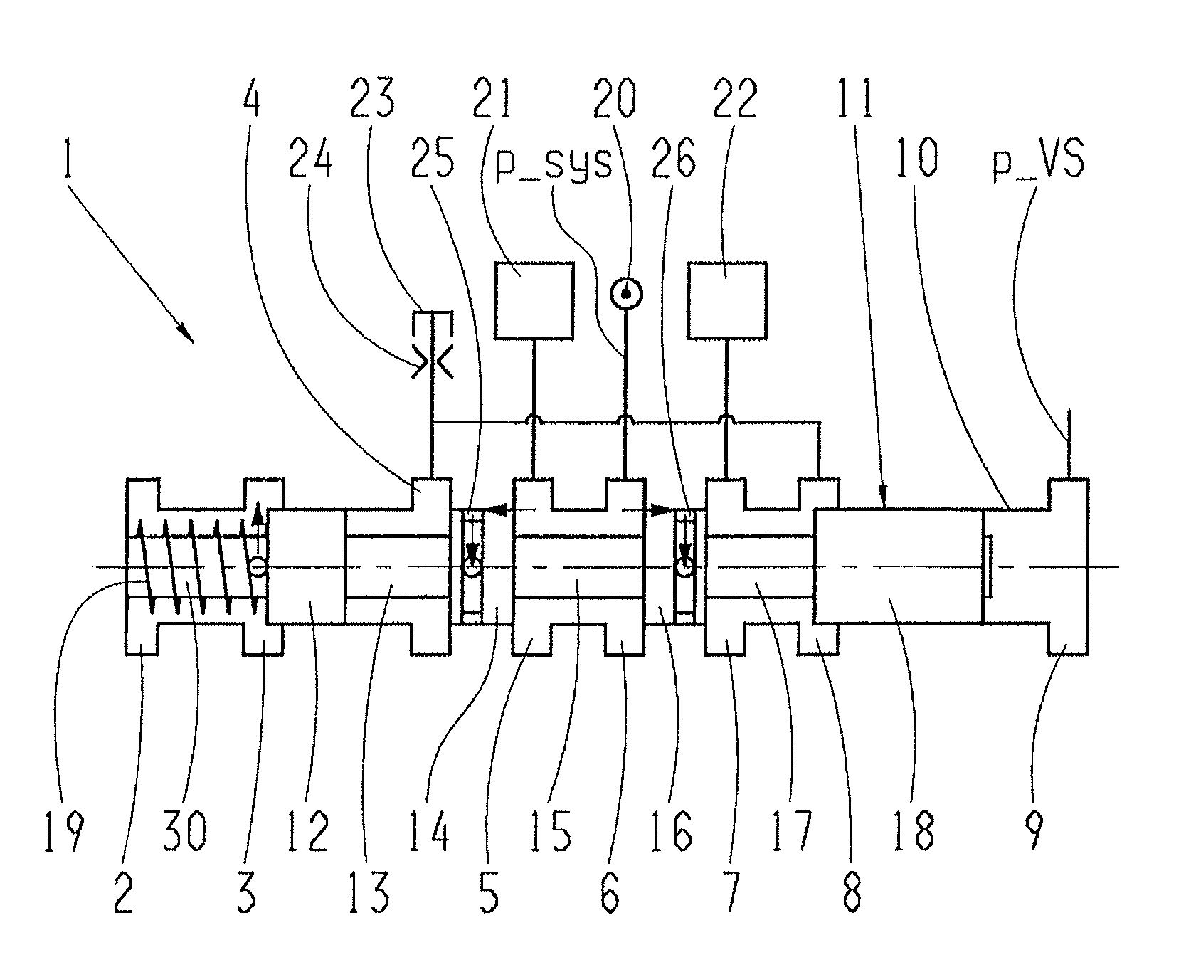
[0033]FIG. 1 shows a longitudinally sectioned view of a first example embodiment of a valve device 1 with a valve housing 10 having a plurality of shifting tongues 2 to 9 and a valve slide 11 arranged to move longitudinally in the valve housing 10. The valve slide 11 is designed with diameter sections 12 to 18 that co-operate, respectively, with the shifting tongues 2 to 9 depending on the axial position of the valve slide within the valve housing 10, and with a further diameter section 30, such that the diameter sections 12 and 14 delimit a section 13 with reduced diameter, the diameter sections 14 and 18 delimit a reduced-diameter section 15, and the diameter sections 16 and 19 delimit a reduced-diameter section 17 in the axial direction.

[0034]In its end position associated with the shifting tongue 2, the valve slide 11 is acted upon by the spring force of a spring device 19, which acts in opposition to a pressure force component resulting from a control pressure p_VS which can be...

Example

[0043]FIGS. 4 and 5 show a second example embodiment of the valve device 1, which differs from the example embodiment according to FIGS. 1 to 3 essentially only in that the design of the valve slide 11 is partly different, and for this reason the description given below will deal only with the differences between the two example embodiments of the valve device 1 while in relation to the further functions of the valve device 1 shown in FIGS. 4 and 5 reference should be made to the description of FIGS. 1 to 3.

[0044]The valve slide 11 of the valve device 1 in FIGS. 4 and 5 is made without the two diameter sections 13 and 14 by means of which, in the valve device 1 according to FIGS. 1 to 3, the tank shifting tongue 4 can be connected to or separated from the working pressure shifting tongue 5. In the version of the valve device 1 in FIGS. 4 and 5, in the switching position of the valve slide 11 shown in FIG. 4 the tank shifting tongue 4 is separated by the delimiting diameter section 1...


PUM


Abstract

A valve device which comprises a valve housing having a plurality of shifting tongues and a valve slide that can move longitudinally in the valve housing. The valve slide is made with diameter sections which co-operate with the shifting tongues depending on an axial position of the valve slide. At least one of the diameter sections is made with at least one, at least approximately groove-like recess that extends in the circumferential direction of the valve slide. The groove-like recesses are functionally connected to an axial bore extending in the valve slide essentially in the axial direction, by way of at least one radial bore extending at least approximately in the radial direction in the valve slide.

Description

[0001]This application claims priority from German patent application serial no. 10 2011 084 932.7 filed Oct. 21, 2011.FIELD OF THE INVENTION[0002]The invention concerns a valve device with a valve housing having a plurality of shifting tongues.BACKGROUND OF THE INVENTION[0003]In valve devices known from practice, which are made with a valve housing having a plurality of shifting tongues and a valve slide arranged to move longitudinally in the valve housing, depending on the geometry of the valve housing and the valve slide a pressure field is formed around the valve slide which is not symmetrical. Among other things the pressure field depends on the geometric shape of the valve slide, for example whether it is conical, straight or designed cylindrically. Furthermore, the pressure field also depends on bevels formed in the area of the valve housing bore. An unsymmetrical pressure field is formed, in particular, when shifting tongues of the valve housing are produced by a casting pro...

Claims


Application Information

Patent Timeline
IPC IPC(8): F16K1/00
CPCF16K27/041F16K11/0716Y10T137/8663
Inventor SCHMIDT, THILO
Owner ZF FRIEDRICHSHAFEN AG
Why Eureka
Try Eureka