Fuel injector and method for the manufacture and/or assembly of a nozzle needle assembly

A fuel injector and fuel injection system technology, which is applied to fuel injection devices, special fuel injection devices, machines/engines, etc., can solve problems such as reversal of the movement direction, and achieve the effect of simplifying the structure.

Inactive Publication Date: 2012-11-14
ROBERT BOSCH GMBH
View PDF8 Cites 2 Cited by
  • Summary
  • Abstract
  • Description
  • Claims
  • Application Information

AI Technical Summary

Problems solved by technology

The coupling thus causes a reve

Method used


Image

  • Fuel injector and method for the manufacture and/or assembly of a nozzle needle assembly
  • Fuel injector and method for the manufacture and/or assembly of a nozzle needle assembly

Examples


Embodiment Construction

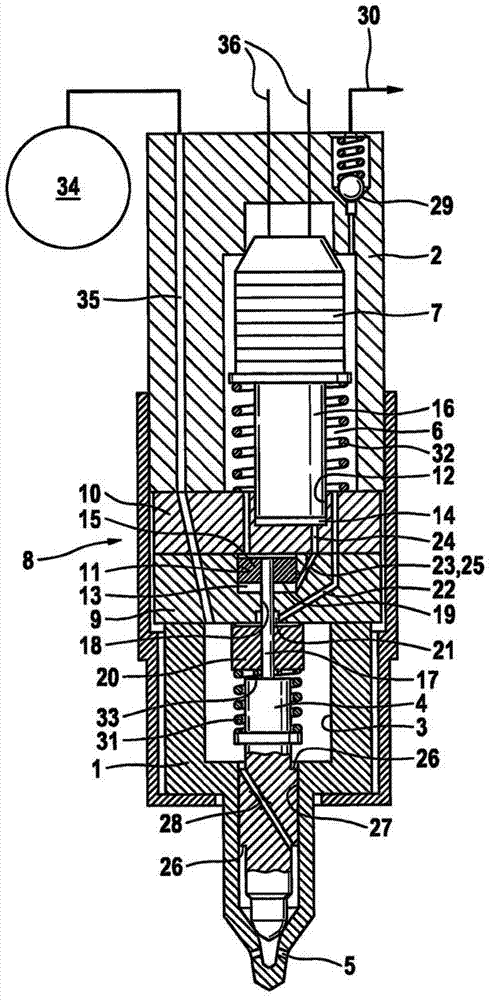
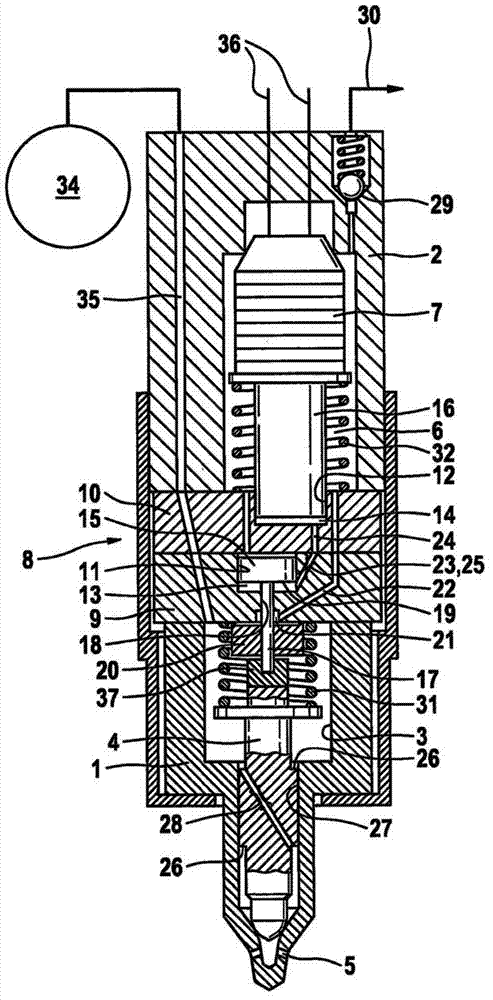
[0025] figure 1The fuel injector shown in longitudinal section has a nozzle body 1 for accommodating a nozzle needle 4 and an injector body 2 for accommodating a piezoelectric actuator 7 for actuating the nozzle needle 4 . The nozzle needle 4 is accommodated in the high-pressure bore 3 of the nozzle body 1 in a reciprocating linear motion, so that at least one nozzle hole 5 formed in the nozzle body 1 can be opened or closed by the stroke of said nozzle needle. If the nozzle needle 4 is in its open position, fuel under high pressure is injected through at least one injection opening 5 into the combustion chamber of the internal combustion engine. Fuel is delivered to the fuel injectors from a high pressure accumulator 34 , now a common accumulator conduit (common rail). Formed in the injector body 2 is an inlet channel 35 through which the fuel passes into the high-pressure bore 3 and thus reaches the at least one injection opening 5 .

[0026] In order to operate the nozzle...


PUM


Abstract

The invention relates to a fuel injector for a fuel injection system, in particular a common rail injection system, having a nozzle body (1) and having an injector body (2), wherein in the nozzle body (1) there is formed a high-pressure bore (3) for accommodating a nozzle needle (4) which can perform a stroke movement and by means of the stroke movement of which at least one injection opening (5) can be opened up or closed off, and wherein in the injector body (2) there is formed a low-pressure chamber (6) for accommodating a piezoelectric actuator (7), which low-pressure chamber can be or is hydraulically coupled via a coupling device (8) to the nozzle needle (4) in such a way that the nozzle needle (3) assumes the closed position thereof when the piezoelectric actuator (7) is electrically discharged. According to the invention, the coupling device (8) comprises a first and a second disk-shaped coupler body (9, 10) with in each case one cylinder bore (11, 12) for accommodating in each case one coupler piston (15, 16) which delimits a coupler chamber (13, 14). The invention also relates to a method for the manufacture and/or assembly of a nozzle needle assembly for a fuel injector.

Description

technical field [0001] The invention relates to a fuel injector having the features of the preamble of claim 1 for a fuel injection system, in particular a common rail injection system, which injects fuel into a combustion chamber of an internal combustion engine . The invention also relates to a method for producing and / or installing a nozzle needle assembly which can be used in particular in such a fuel injector. Background technique [0002] A fuel injector of this type is known, for example, from the publication DE 10 2008 002 417 A1. The fuel injector described therein includes a piezoelectric actuator disposed within a relatively unpressurized actuator chamber. The actuator is hydraulically coupled to the nozzle needle of the injector so that the nozzle needle assumes its closed position when the piezo actuator is electrically unloaded, and when the piezo actuator is switched on Flips into the open position when on power. That is, the opening stroke of the nozzle n...

Claims


Application Information

Patent Timeline
IPC IPC(8): F02M63/00F02M51/06
CPCF02M2200/703F02M51/0603F02M2200/704F02M63/0026Y10T29/494
Inventor N·艾森门格尔H-C·马格尔
Owner ROBERT BOSCH GMBH
Why Eureka
Try Eureka