Planetary gear system

a gear system and planetary technology, applied in the direction of gearing details, machines/engines, gearing, etc., can solve the problems of gear system and power loss, and achieve the effects of reducing the agitation resistance of lubricating oil, reducing the power loss of the planetary gear system, and efficient discharg

Active Publication Date: 2013-04-25
KAWASAKI HEAVY IND LTD
View PDF4 Cites 54 Cited by
  • Summary
  • Abstract
  • Description
  • Claims
  • Application Information

AI Technical Summary

Benefits of technology

The planetary gear system described in this patent allows for efficient removal of lubricant from its key parts, reducing friction and minimizing energy waste.

Problems solved by technology

The technical problem addressed in this patent is how to reduce the power loss in planetary gear systems used in aircraft engines, in order to increase fuel efficiency and save operational costs while maintaining environmental control. This involves minimizing the agitation resistance caused by the lubricating oil circulated throughout the system, with methods including its efficient removal through the use of a double-helical gear and the placement of a baffle between adjacent planets to prevent swirl flow formation.

Method used


Image

  • Planetary gear system
  • Planetary gear system
  • Planetary gear system

Examples


Embodiment Construction

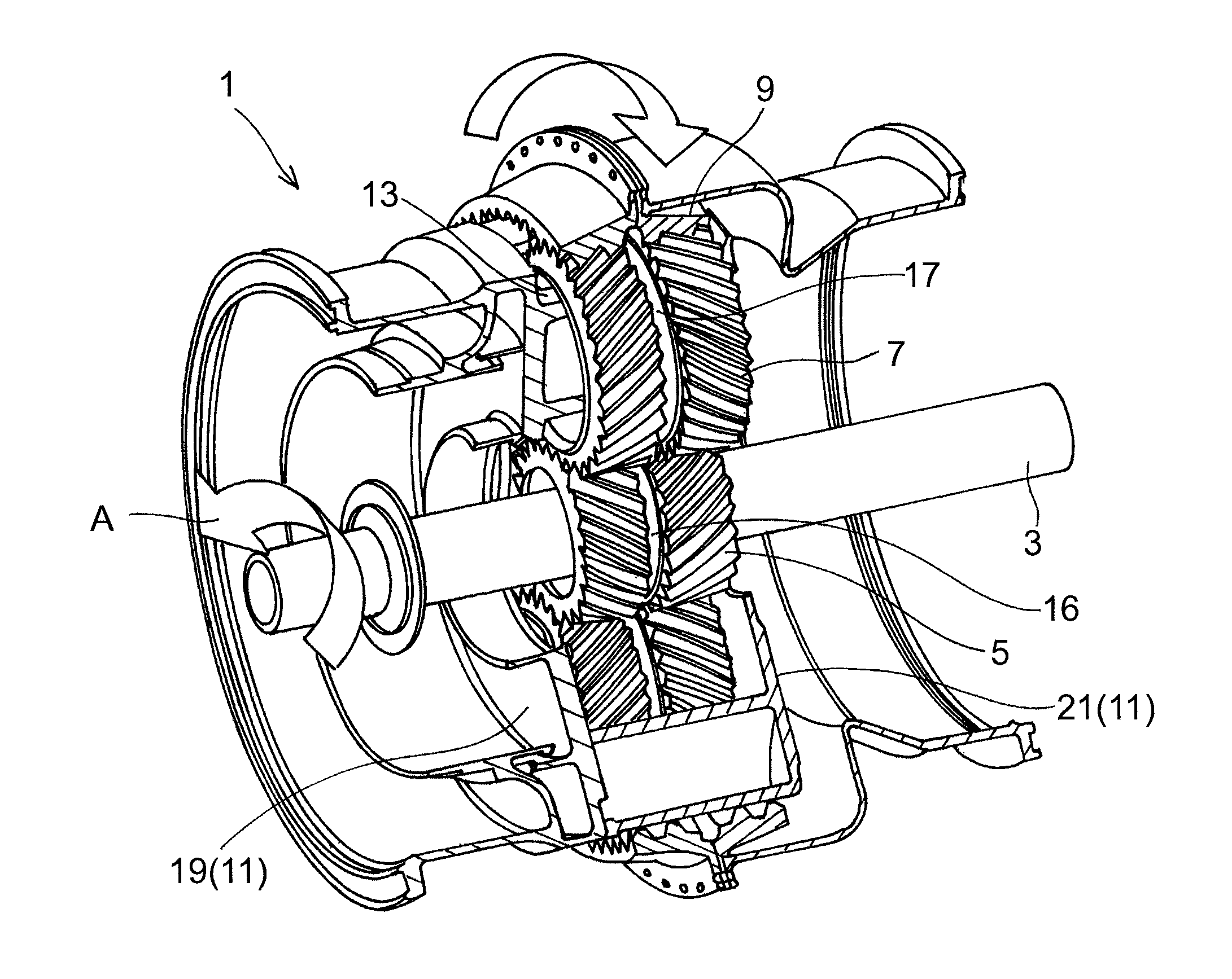
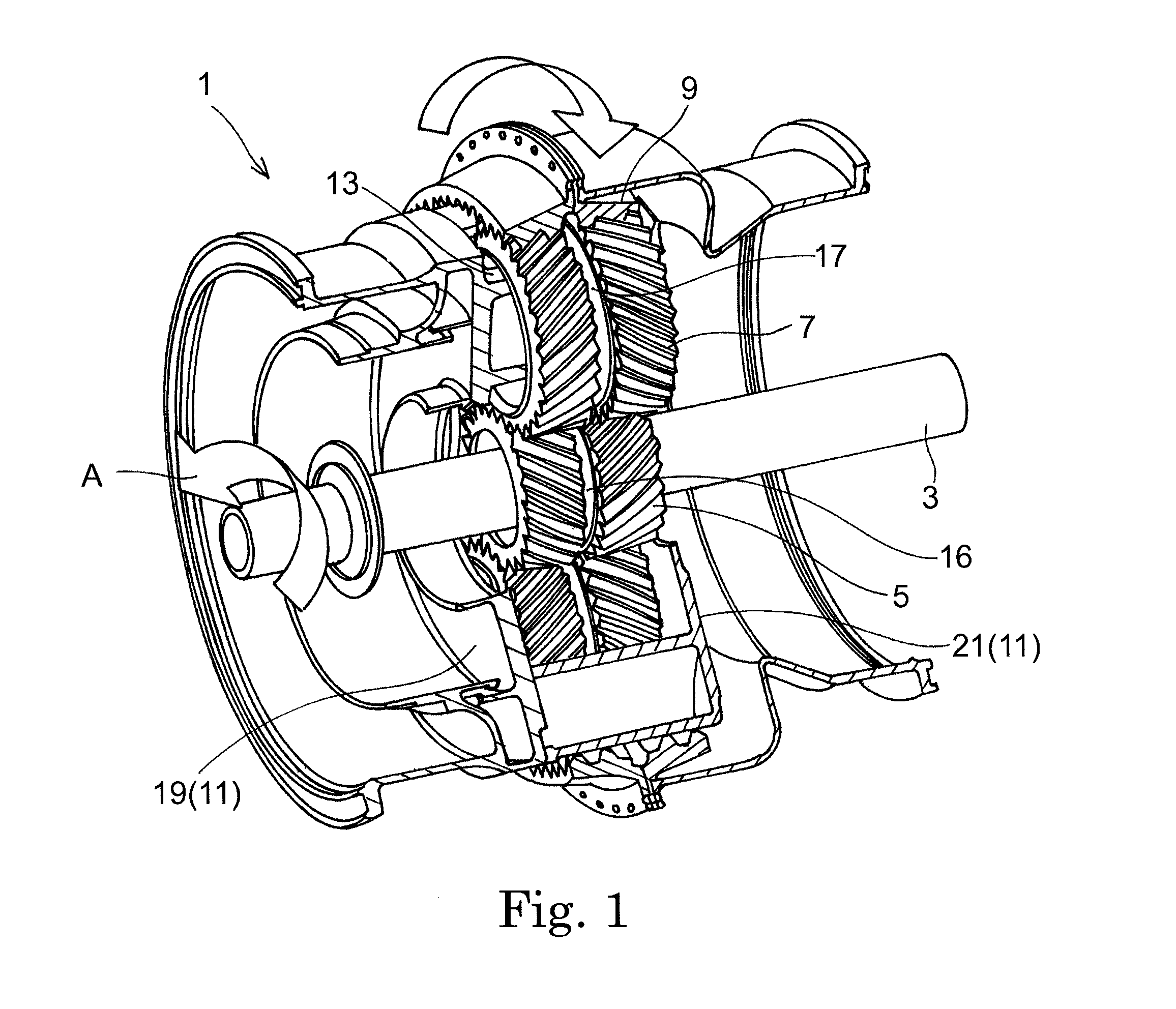
[0026]Hereinafter, a preferred embodiment of the present invention is described with reference to the accompanying drawings. FIG. 1 is a perspective view showing a planetary gear system 1 according to one embodiment of the present invention. The planetary gear system 1 is installed in an aircraft engine, and transmits power of an input shaft 3 as two outputs. It should be noted that in the description below, along the axial direction of the planetary gear system 1, one side of the planetary gear system 1, at which side the engine is disposed (i.e., the lower left side in FIG. 1), is referred to as a front side, and the opposite side is referred to as a rear side.

[0027]The planetary gear system 1 is configured as a double-row gear mechanism, which includes: a central sun gear 5; planet gears 7; and an outer ring gear 9. The sun gear 5 is a double helical gear including a pair of helical gears and having sets of external teeth, the sets of external teeth being inclined in respective d...


PUM


Abstract

A planetary gear system (1) includes: a sun gear (5) having external teeth; a plurality of planet gears (7) having external teeth, each planet gear meshing with the sun gear; a ring gear (9) having internal teeth, the ring gear meshing with the planet gears; and a baffle unit (35) disposed between the planet gears which are adjacent to each other, the baffle unit having side faces (37F, 37R) positioned near the respective planet gears. The baffle unit (35) has: oil supply holes (47) which are formed in a tip portion (41) facing an outer periphery of the sun gear (5) and which jet out lubricating oil (OL) to mesh positions (43, 45) between the sun gear and the planet gears; and a collection opening (55) which is formed in at least one of the side faces and through which the lubricating oil (OL) that has been jetted out is collected into the baffle unit (35).

Description


Claims


Application Information

Patent Timeline
Owner KAWASAKI HEAVY IND LTD
Why Eureka
Try Eureka