Free-standing action target mechanism for firearm training

a free-standing action, target technology, applied in the direction of movable targets, weapons, target ranges, etc., can solve the problems of affecting the use of firearms, and lacking target devices or mechanisms, etc., to achieve the effect of resisting damag

Inactive Publication Date: 2013-05-02
LARUE MARK C
View PDF5 Cites 27 Cited by
  • Summary
  • Abstract
  • Description
  • Claims
  • Application Information

AI Technical Summary

Benefits of technology

[0011]A spall unit incorporates a spall support structure which defines a rectangular shaped opening and also receives the support post and has a first position establishing a moveable relation with the support post and a second position establishing a gripping or binding relation with the support post. The spall assembly is preferably composed of

Problems solved by technology

Portable firearm targets are also frequently provided, which can be set up for shooting activities in a short period of time; however these types of target devices or mechanisms are typically lacking from the standpoint of durability and are often damaged and rendered useless during firearm shooting activities.
Silh

Method used


Image

  • Free-standing action target mechanism for firearm training
  • Free-standing action target mechanism for firearm training
  • Free-standing action target mechanism for firearm training

Examples


Embodiment Construction

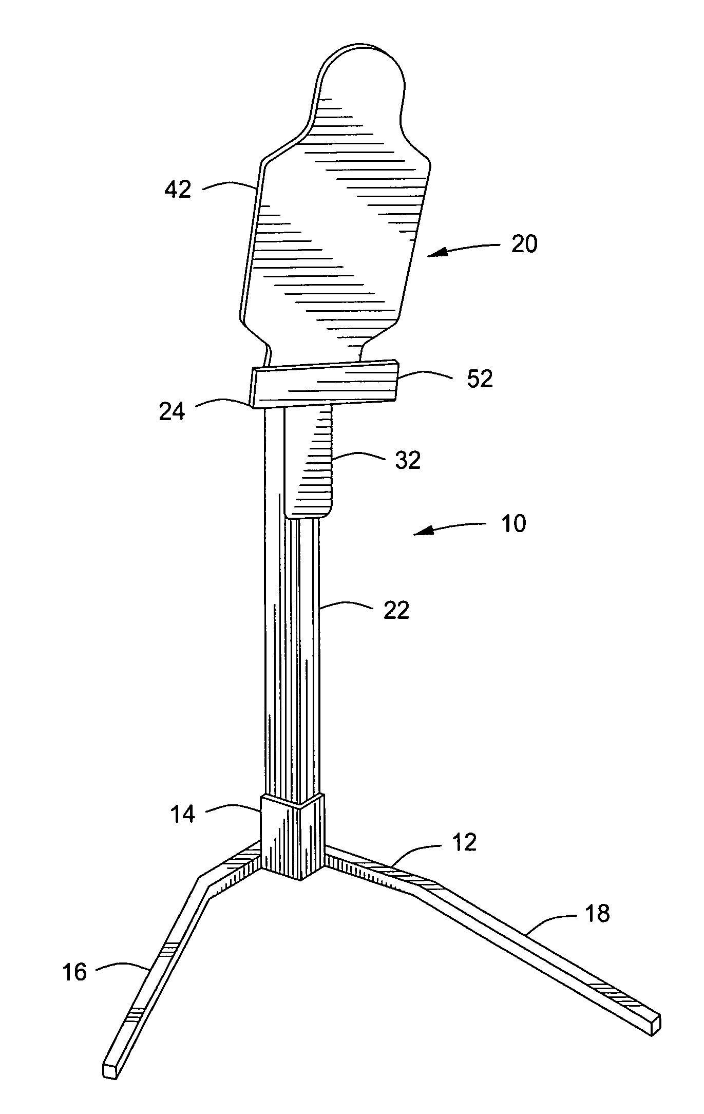
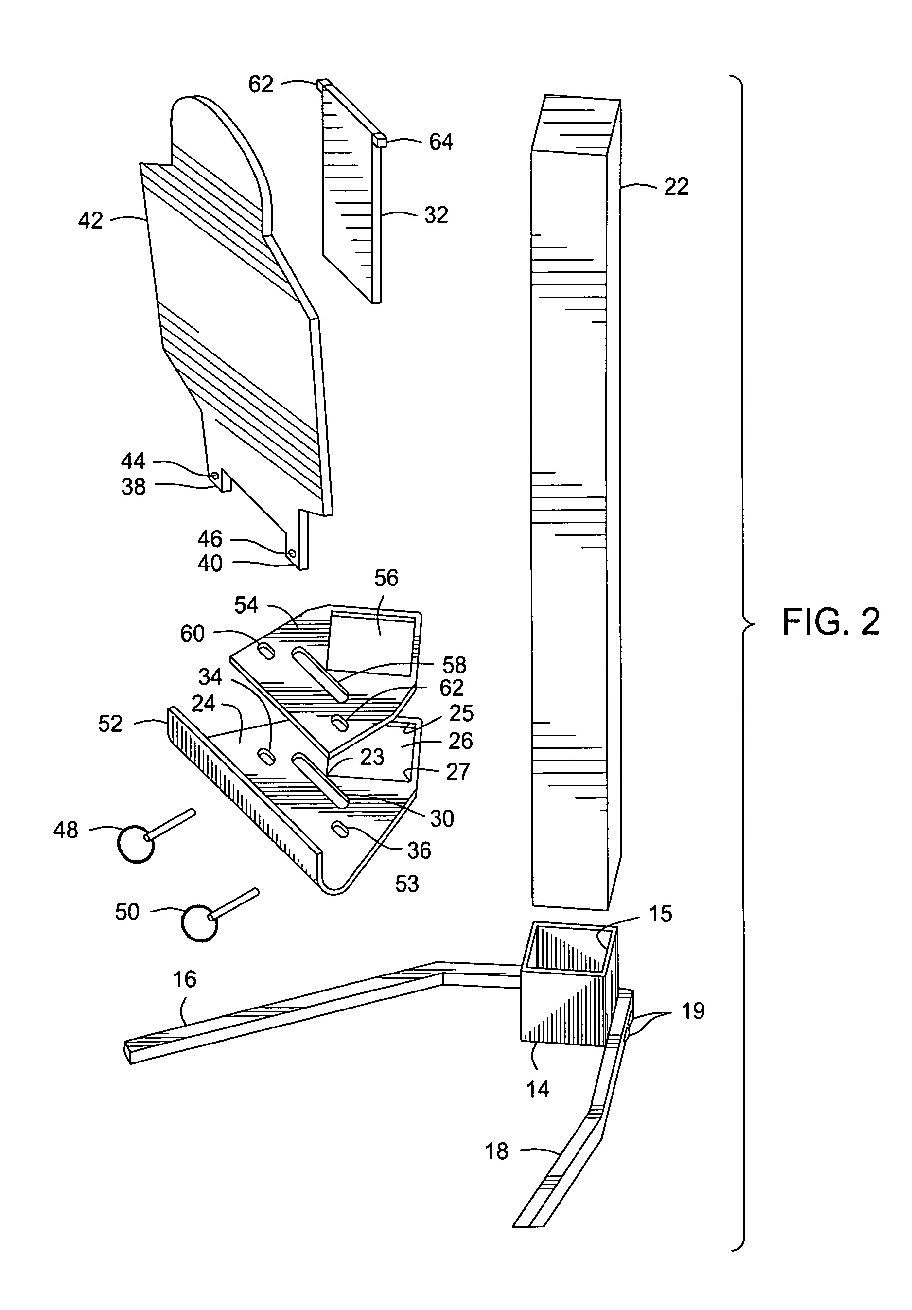
[0018]Referring now to the drawings and first to FIGS. 1 and 2, a target mechanism embodying the principles of the present invention is shown generally at 10 and incorporates a support base assembly, shown generally at 12, and having a post support member 14 of tubular form that defines a post support receptacle 15. The post support receptacle may be open completely through or, if desired, may be closed by a lower closure plate or panel. The post support receptacle 15 preferably has a generally rectangular or square cross-sectional configuration, corresponding to the cross-sectional configuration of a 4″×4″ wood post 22, or may have any other tubular form, such as cylindrical, octagonal, triangular, etc., as desired. To the lower end portion of the post support member 14 is mounted a pair of support legs 16 and 18 that extend laterally and forwardly from the post support member.

[0019]Each of the support legs is preferably an independent leg member that is mounted to the post support...


PUM


Abstract

A free-standing post supported target mechanism has a support post of a defined cross-sectional geometry. A baseplate defines a post opening receiving the support post and has a first orientation permitting movement of the baseplate along the length of the support post and a second orientation establishing a gripping relation with the support post. A spall plate defines a post opening receiving the support post and has a first orientation permitting movement of the spall plate along the length of the support post and a second orientation establishing a gripping relation of the spall plate with the support post. A target plate engages the baseplate and the spall plate and is secured by a locking member. A target base defines a receptacle receiving and supporting the support post and establishes a weight-forward condition that offsets the rearward forces of bullet impact.

Description

BACKGROUND OF THE INVENTION[0001]1. Field of the Invention[0002]The present invention relates generally to target devices that are employed by firearm users for the purpose of marksmanship training and practice, for general shooting activities and for sighting in the various types of sighting devices that are mounted on firearms. More particularly, the present invention concerns a portable free-standing target mechanism that presents a silhouette or other type of target on a bullet resistant panel that enables a firearm user to determine when the target has been struck, thus verifying the accuracy of firearm sighting and shooting activities. Even more specifically, the present invention concerns a portable target mechanism that can be set up or taken down in a short period of time and requires little or no preparation of the site, except for the choice of a site having a backdrop that is capable of stopping any bullets that should miss the target.[0003]2. Description of the Prior Ar...

Claims


Application Information

Patent Timeline
IPC IPC(8): F41J1/10
CPCF41J1/10
Inventor LARUE, MARK C.
Owner LARUE MARK C
Why Eureka
Try Eureka