Fatigue Resistant Rotary Shouldered Connection and Method

a rotary shouldered connection and fatigue resistance technology, applied in the direction of hose connection, screw threaded joint, mechanical apparatus, etc., can solve the problem that the equivalent api prior art connection subjected to the same testing procedure failed after less than 2 million testing cycles, and achieve the effect of maximizing the space available, and maximizing the space availabl

Inactive Publication Date: 2006-09-28
GRANT PRIDECO LP
View PDF6 Cites 34 Cited by
  • Summary
  • Abstract
  • Description
  • Claims
  • Application Information

AI Technical Summary

Benefits of technology

[0020] A related object of the present invention is to maintain a ratio of the thread lead to the untruncated thread height as small as possible consistent with the size of the outside and inside diameters of the threaded tubular bearing the connection to maximize the space available for formation of a relatively large thread root between adjacent thread teeth in the connection.
[0021] It is also an object of the present invention to maintain a ratio of the thread lead, in threads per axial length, to the value of the thread root truncation that is as small as possible consistent with the size of the outside and inside diameters of the threaded tubular bearing the connection to maximize the space available for formation of a relatively large thread root between adjacent thread teeth in the connection.
[0022] An object of the present invention is to maintain a ratio of the thread lead to the length of the root radius (or root radii) as small as possible consistent with the size of the outside and inside diameters of the threaded tubular bearing the connection to maximize the space available for formation of a relatively large thread root between adjacent thread teeth in the connection.
[0023] A further object of the present invention is to maintain a ratio of the untruncated thread height to the root

Problems solved by technology

Equivalent API prior art connections subjected to the same tes

Method used


Image

  • Fatigue Resistant Rotary Shouldered Connection and Method
  • Fatigue Resistant Rotary Shouldered Connection and Method
  • Fatigue Resistant Rotary Shouldered Connection and Method

Examples


Embodiment Construction

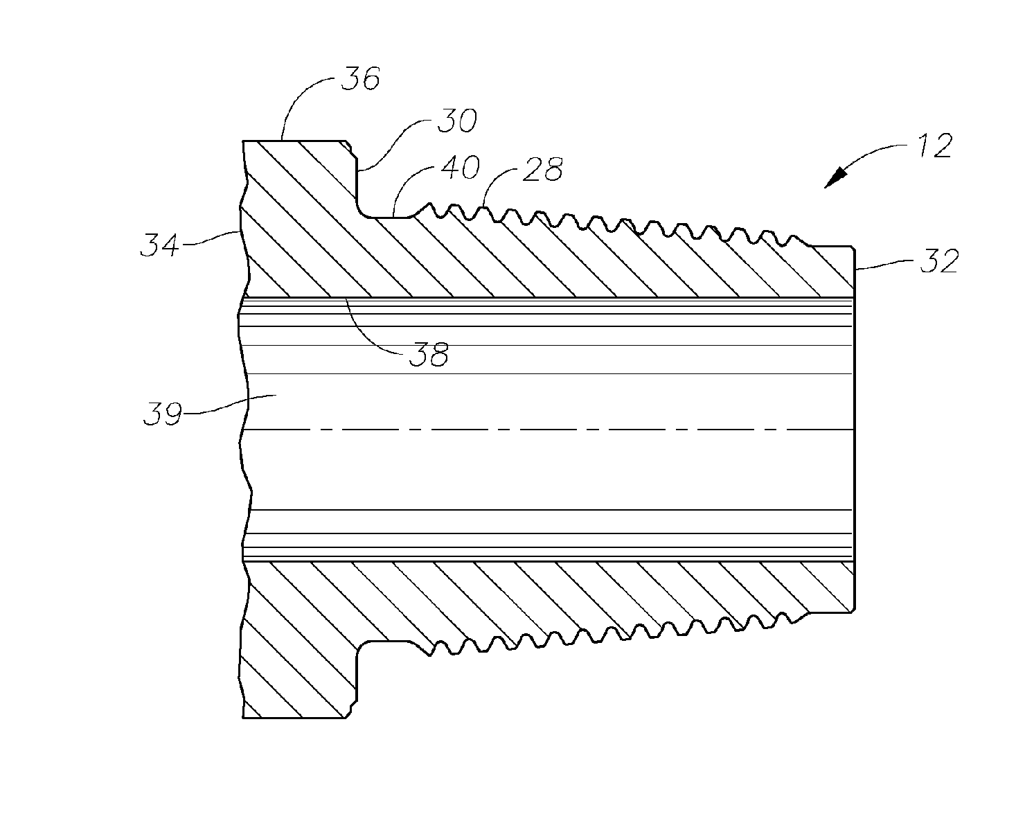
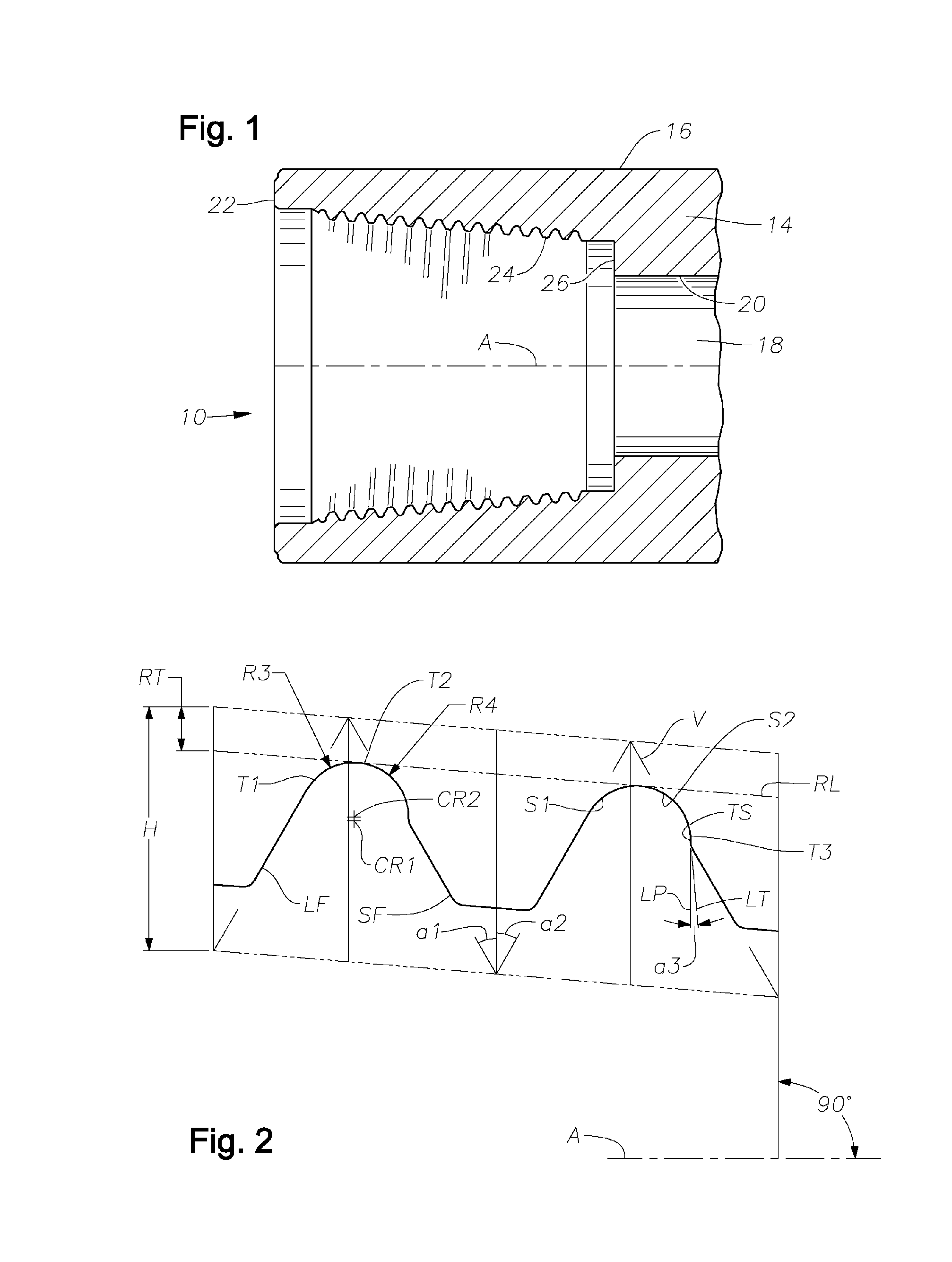
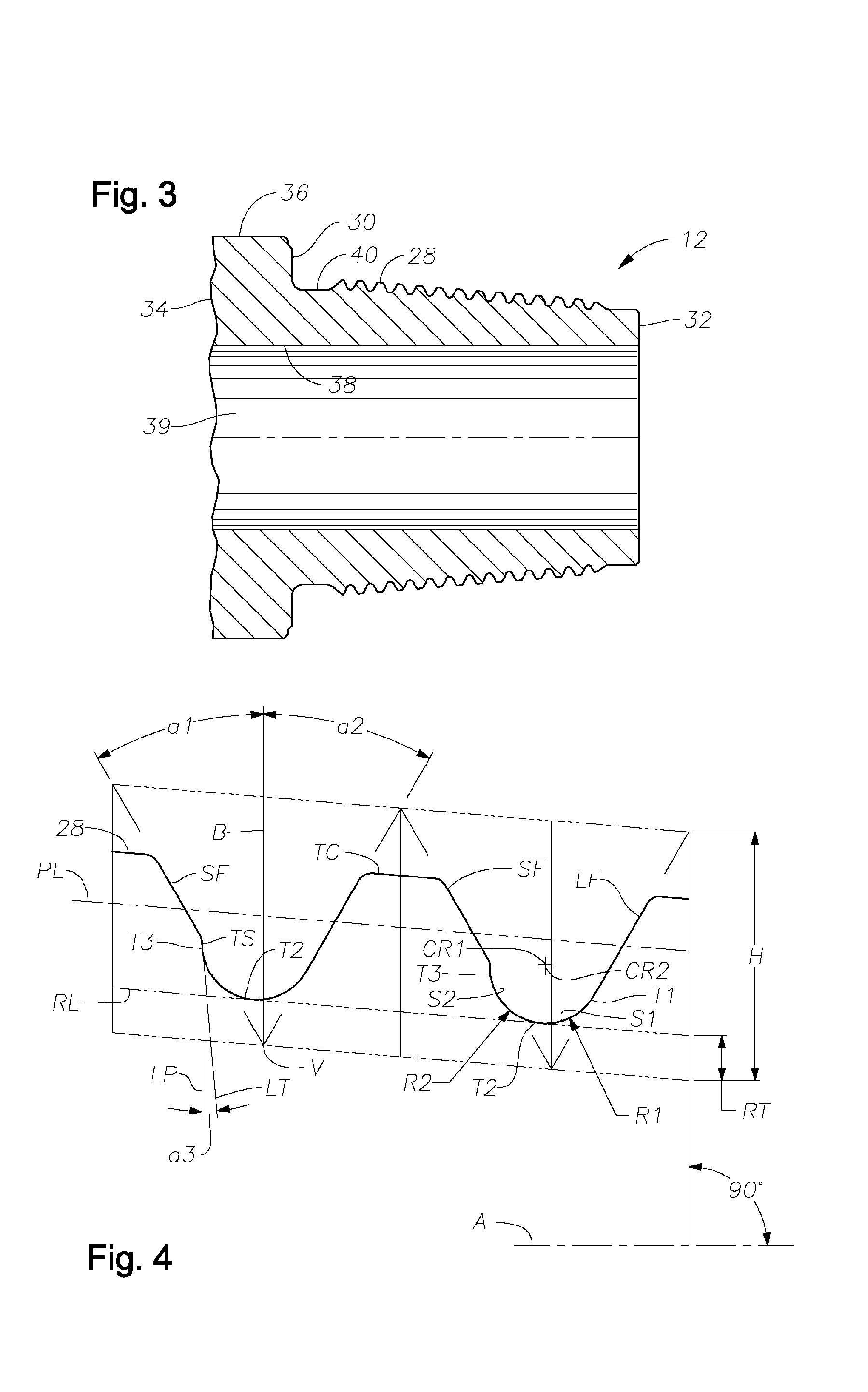
[0037] An internally threaded box connection of the present invention is indicated generally at 10 in FIG. 1. The box connection 10 may be the threaded end of a well pipe tubular that serves as a drill collar or other tubular component forming a part of the bottom hole assembly of a drill stem. The box connection 10 is designed to receive and connect with an externally threaded pin illustrated in FIG. 3 and indicated generally at 12. The pin 12 and box 10 are provided with threads that draw the two components together axially when they are rotated together with a conventional torquing device (not illustrated).

[0038] The box 10 is formed at one axial end of a tubular body 14 having an external cylindrical surface 16 coaxially disposed about a central opening 18 defined within an internal cylindrical surface 20. The central opening 18 extends through the body 14 and terminates in a pin end connection (not illustrated) such as the connection illustrated in FIG. 3. When employed as a d...


PUM


Abstract

Threaded connections are provided with a thread form that permits the construction of enlarged root radii between adjacent threads. Relatively coarse thread leads formed along conical surfaces with relatively extended tapers cooperate with relatively tall thread heights and an enlarged root radius (or radii) to produce a fatigue resistant, rotary-shouldered connection that can be assembled with reasonably attainable high torque forces. The ratios between the thread lead, measured in threads per inch, as the numerator, and denominators comprising the untruncated thread height of the thread, and/or the root truncation and/or the root radius (or radii) are maintained at low values compared to those existing in conventional prior art connections. The ratio of the untruncated thread height to the root radius (or radii) is also retained at a relatively low value as compared to that existing in many prior art configurations. The connection design produces an unexpectedly high resistance to fatigue damage or failure. The connection may be employed in any rotary-shouldered connection and is particularly effective in preventing fatigue damage in the stiffer components of drill stem assemblies including single shoulder and double shoulder drill collar connections.

Description

BACKGROUND OF THE INVENTION [0001] 1. Field of the Invention [0002] The present invention relates primarily to threaded connections employed to join together the ends of relatively stiff, heavy tubular pipe members employed to drill through earthen formations. More particularly, the present invention relates to a thread for use in the pin and box connection of drill collars, subassemblies, heavyweight drill pipe, or other relatively stiff tubular components of a drill stem assembly. [0003] 2. Setting of the Invention [0004] Heavy, relatively stiff tubular bodies are employed at the bottom of the drill string primarily to apply weight to the drill bit, to maintain the drill string in tension and to monitor at and assist in controlling the drilling process. These heavier components at the bottom of the drill string are frequently referred to as a bottom hole assembly. The bodies in the bottom hole assembly usually include tubular drill collars, drilling, steering and monitoring subass...

Claims


Application Information

Patent Timeline
IPC IPC(8): F16L25/00
CPCE21B17/042E21B17/16F16L15/001
Inventor MURADOV, ANDREI
Owner GRANT PRIDECO LP
Why Eureka
Try Eureka