
Suspension Device for a Vehicle

Active Publication Date: 2013-05-02
KOKU AHMET BUGRA +2
View PDF17 Cites 16 Cited by
  • Summary
  • Abstract
  • Description
  • Claims
  • Application Information

AI Technical Summary

Benefits of technology

This patent describes a suspension system that allows for fully automated and unmanned vehicles to move upside down and have extreme off-road capabilities. It is also suitable for all types of robots that can perform multi-functional movements. The technical effects of this invention make it optimal for use in unmanned vehicle development.

Problems solved by technology

This limited operational capability of the suspensions known in the prior art, makes them impossible to be used in new robotics and unmanned vehicles technologies where the vehicle is to operate upside down or not and is not subject to deep hole problem.
Besides this technical deficiency, conventional suspensions of the prior art cannot function properly when the wheels of a vehicle encounter with a deep hole.
In this situation, because of their limited functioning capabilities, the suspensions stay in their elongated state and cease to perform their functions against a deep hole.
However, these applications have the similar technical problem.
On uneven road surfaces or while encountering a deep hole situation, the springs of the said systems try to work against each other causing both excessive usage of material and work loss instead of bringing any technical advantage and proper solution for the problem.
In addition to all these present technical problems, the near future is likely to create a new technical problem for the known suspensions in the prior art in respect to ever-growing robotics technology that makes it possible to develop more kinds of unmanned vehicles and other types of robots.

Method used


Image

  • Suspension Device for a Vehicle
  • Suspension Device for a Vehicle
  • Suspension Device for a Vehicle

Examples


Embodiment Construction

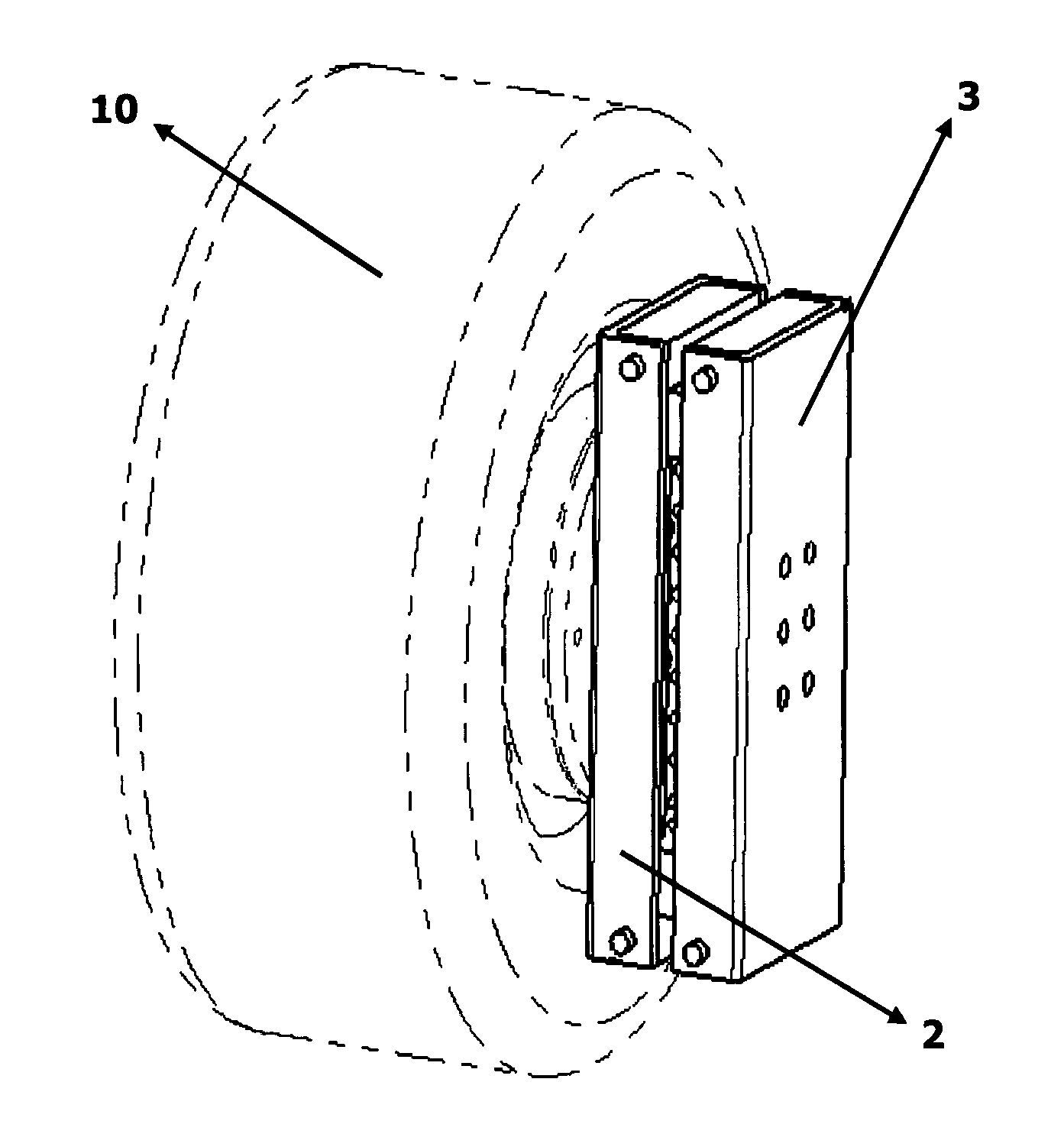
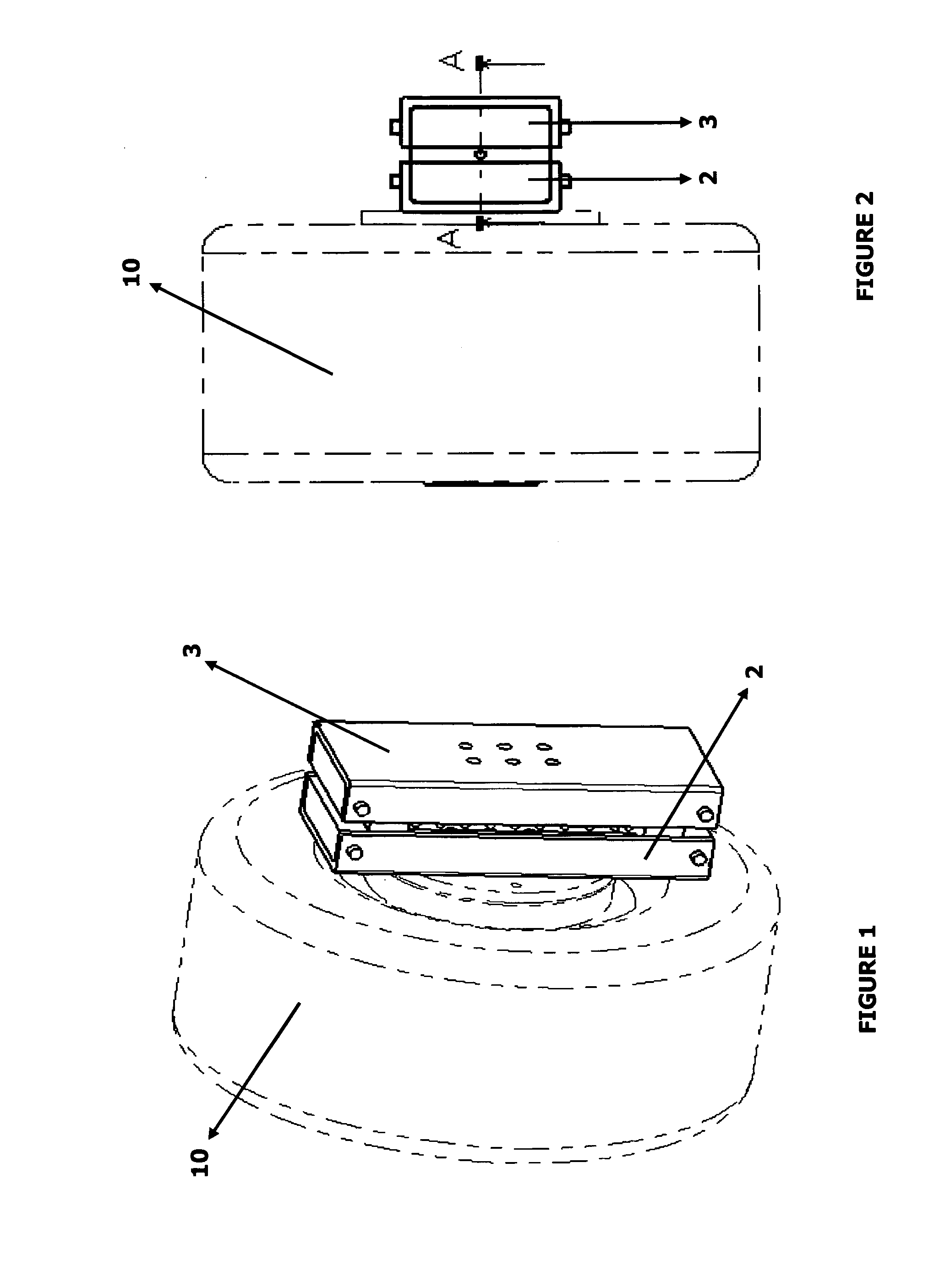
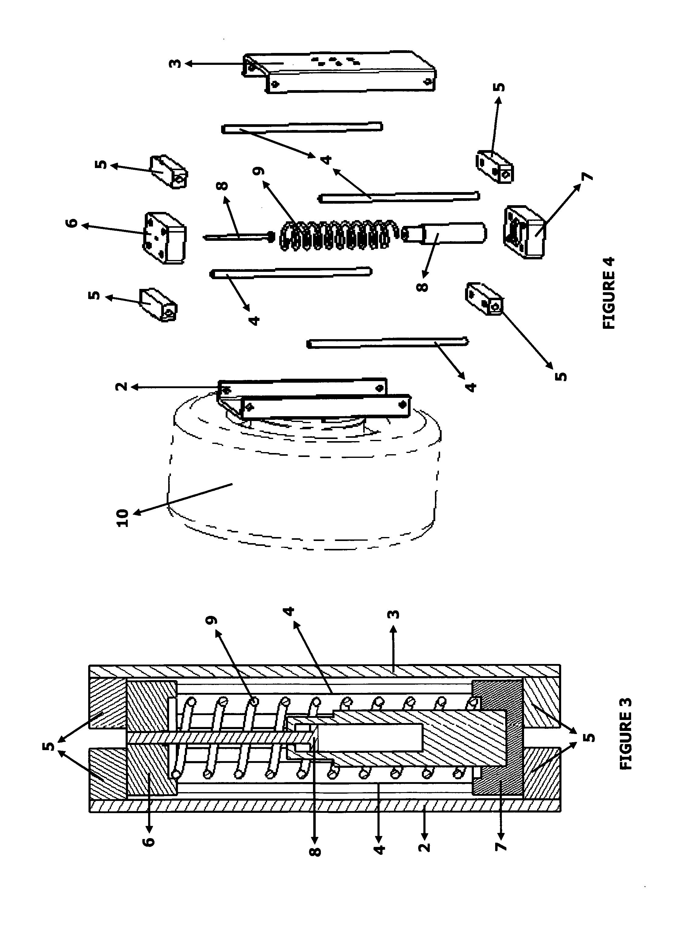
[0031]Bilateral Operating Suspension (1) described in the present invention consists of 8 main parts;

[0032]Suspension tire structure connector (2)

[0033]Suspension vehicle body connector (3)

[0034]Slider beds (4)

[0035]Slider stoppers (5)

[0036]Upper end slider (6)

[0037]Lower end slider (7)

[0038]Piston (8)

[0039]Spring (9)

[0040]The bilateral operating suspension (1) is assembled to the vehicle body and the tire structure (10) by the suspension vehicle body connector (3) and suspension tire structure connector (2). The suspension vehicle body and suspension tire structure connectors (2, 3) also function as the casing of the other components (4, 5, 6, 7, 8 and 9) of the bilateral operating suspension (1).

[0041]Inside the casing formed by the suspension vehicle body connector (3) and suspension tire structure connector (2), slider beds (4) are fixed to the suspension vehicle body connector (3) and suspension tire structure connector (2) by the slider stoppers (5). The upper end slider (6) a...


PUM


Abstract

This invention relates to a suspension particularly for every type of land vehicles and additionally for robotic applications, which can be used in bilateral operations, such as fully automated unmanned vehicles that can be driven on both sides (up and down) or in robots which can be capable of executing multi functional movements.

Description

RELATED FIELD OF THE INVENTION[0001]This invention relates to a suspension particularly for every type of land vehicles and additionally for robotic applications, which can be used in bilateral operations, such as fully automated unmanned vehicles that can be driven on both sides (up and down) or in robots which can be capable of executing multi functional movements.BACKGROUND OF THE INVENTION (PRIOR ART)[0002]All types of land vehicles in the prior art are considered as one-sided vehicles since they have a specific orientation (i.e. top and bottom of the vehicle) for proper operation. Hence, their suspensions are designed accordingly to perform only in one direction.[0003]However, with the ever-growing robotics technology, all types of unmanned vehicles and other types of robots begin to intervene into field applications and daily usage. So called advancements in robotics and vehicle technologies makes it a necessity to develop a novel suspension which can provide symmetric perform...

Claims


Application Information

Patent Timeline
IPC IPC(8): B60G3/01
CPCB60G3/01B60G2204/4232B60G2204/30B60G2206/01B60G2206/42
Inventor KOKU, AHMET BUGRAKONUKSEVEN, ERHAN ILHANKUL, MUSTAFA CIHANGIR
Owner KOKU AHMET BUGRA
Learn More