Optical reflector having semi-reflective blades for a position detection device for a helmet, and helmet comprising such a device

a technology of optical reflector and position detection device, which is applied in the direction of optical elements, instruments, and optical elements, which can solve the problems of increasing the cost of detection system, insufficient use of single catadiopter, and hardly utilizable detection signals

Inactive Publication Date: 2013-12-10
THALES SA
View PDF6 Cites 0 Cited by
  • Summary
  • Abstract
  • Description
  • Claims
  • Application Information

AI Technical Summary

Benefits of technology

[0015]The invention relates finally to an optical device for detecting position / orientation of a helmet, said device comprising at least one fixed camera associated with an image processing system, a fixed light source, opto-mechanical means making it possible to produce an image of the light source on the optical axis of the camera and the helmet carrying at least one optical component such as defined above.

Problems solved by technology

The detected signal becomes hardly utilizable if the solar illumination received by the helmet is significant.
However, the levels of solar illumination are still high in the infrared and ultraviolet bands and this type of solution requires specific emission and reception sources which necessarily increase the costs of the detection system.
It is clear that the use of a single catadiopter is insufficient to achieve the helmet's instantaneous position and instantaneous orientation function.
Indeed, it may be demonstrated that any defect in the geometry of the tetrahedron either from the outset or due to an alteration in the structure will not only degrade the measurement accuracy but also introduce new ambiguities in the discrimination of the points.
As an example, an angular deviation of 0.5 mrad in the position of a point of the tetrahedron gives rise to an error of 1 mrad in the measurement.
It is a definite handicap for systems which, being mounted on the user's head, must remain as lightweight as possible.

Method used


Image

  • Optical reflector having semi-reflective blades for a position detection device for a helmet, and helmet comprising such a device
  • Optical reflector having semi-reflective blades for a position detection device for a helmet, and helmet comprising such a device
  • Optical reflector having semi-reflective blades for a position detection device for a helmet, and helmet comprising such a device

Examples


Embodiment Construction

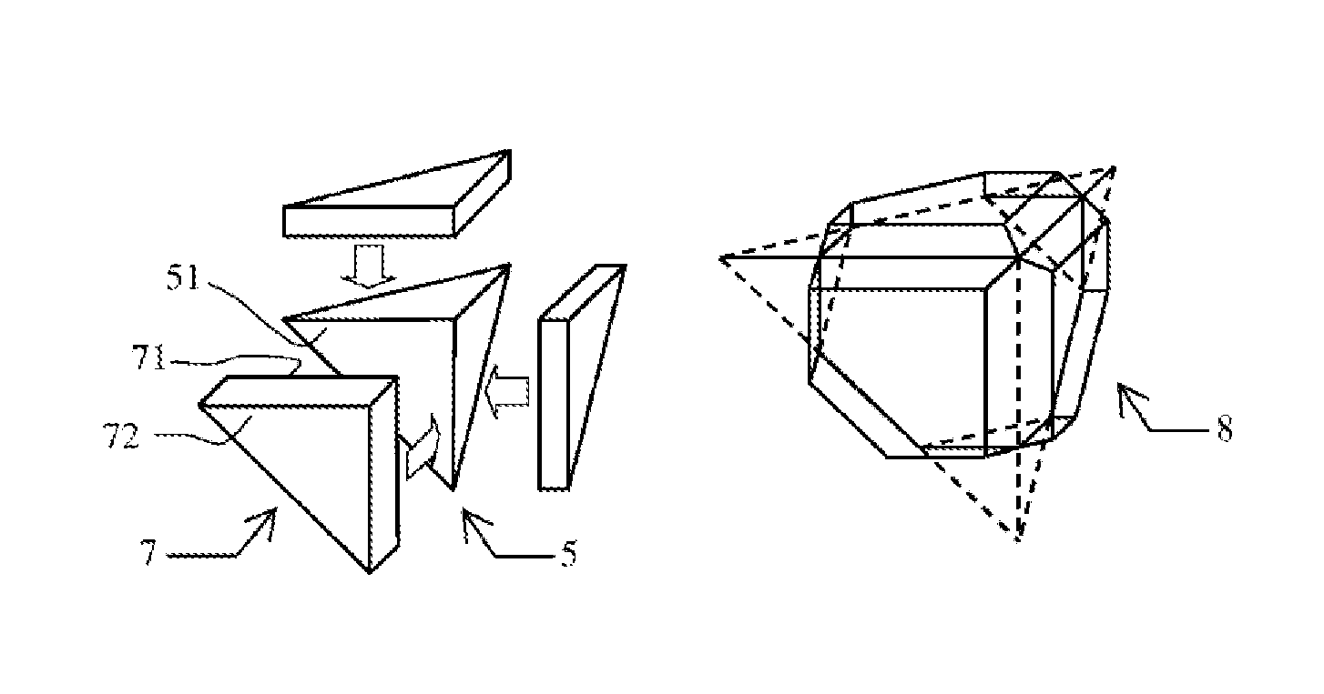
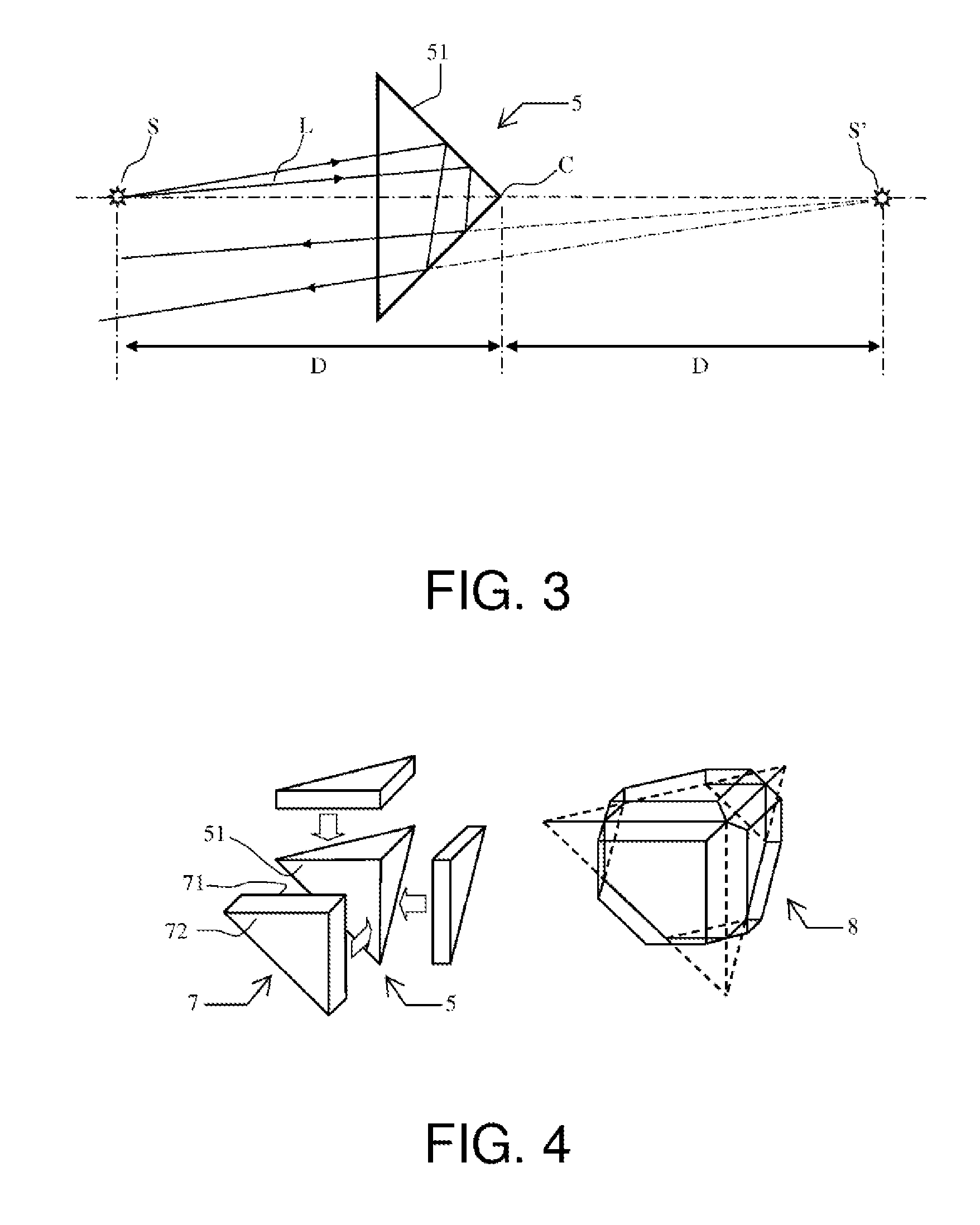
[0025]Instead of positioning four sources in an accurate manner and imaging them, the component according to the invention creates N virtual images of one and the same source S by way of a particular arrangement represented in the two views of FIG. 4. As seen in the left view of FIG. 4, three blades 7 with plane and parallel faces are arranged on the three plane faces 51 of an optical cube corner 5. The first face 71 of each blade 7 is arranged on a face 51, the interface between this first face 71 and the surface 51 comprising a semi-reflecting treatment. The second face 72 of each blade is reflecting.

[0026]The right view of FIG. 4 represents the component 8 according to the invention, once the optical cube corner 5 and the three blades 7 have been assembled and the edges of the optical cube corner folded-down (dashed parts in this view).

[0027]The manner of operation of the optical component according to the invention is described in FIGS. 5 and 6 which represent respectively the i...


PUM


Abstract

The general field of the invention is that of optical position/orientation devices for a helmet and more particularly those whose helmet comprises neither emitters, nor receivers but solely passive optical components, detection of which is ensured by fixed opto-electronic means outside the helmet. The optical component for the optical device for detecting position/orientation of a helmet according to the invention comprises a particular “optical cube corner”. It comprises a prism in the form of a trirectangular trihedron, each of the three plane surfaces of the trihedron comprising a blade with plane and mutually parallel faces, the first face being coincident with the plane surface on which it rests, the interface between this first face and said surface comprising a semi-reflecting treatment.

Description

CROSS-REFERENCE TO RELATED APPLICATIONS[0001]This patent application is a U.S. National Phase Application under 35 U.S.C. §371 of International Application No. PCT / EP2010 / 068749, filed Dec. 2, 2010, entitled OPTICAL REFLECTOR HAVING SEMI-REFLECTIVE BLADES FOR A POSITION DETECTION DEVICE FOR A HELMET, AND HELMET COMPRISING SUCH A DEVICE, which claims priority to French Patent Application No. 0905866, filed Dec. 4, 2009.BACKGROUND OF THE INVENTION[0002]1. Field of the Invention[0003]The field of the invention is that of optical devices for detecting the instantaneous position and instantaneous orientation of the helmet worn by an aircraft pilot. In a general manner, a particular position and orientation of the helmet will be called a posture hereinafter in the text. For certain aeronautical applications, pilots' helmets are furnished with viewing devices making it possible to generate, in the pilot's field of view, information relating to piloting, to navigation or to the weapons syst...

Claims


Application Information

Patent Timeline
Patent Type & Authority Patents(United States)
IPC IPC(8): G01B11/14G01S17/875
CPCF41G3/225G01S17/875G02B5/122G02B27/0093G02B27/144G02B27/145G02B19/0066G02B19/0028
Inventor POTIN, LAURENTROUZES, SIEGFRIEDGERBE, JEAN-PIERRE
Owner THALES SA
Why Eureka
Try Eureka