Flexible Energy Balancing System

a technology of energy balance and flexible energy, applied in the direction of electric generator control, machines/engines, mechanical apparatus, etc., can solve the problems of inefficient systems, high cost, and time-consuming, and achieve the effects of balancing energy, constant power, and prolonged start procedur

Inactive Publication Date:
View PDF1 Cites 13 Cited by
  • Summary
  • Abstract
  • Description
  • Claims
  • Application Information

AI Technical Summary

Benefits of technology

[0020]Again, the base load high pressure steam boiler takes in fuel and burns it to generate high pressure steam to drive the steam turbine generators to produce a constant amount of power. Thus the base load high pressure steam boiler ensures that the STG's are maintained in an operating condition so that a prolonged start procedure is not required if additional steam is produced from the heat recovery steam generators. The base load steam boiler can also provide a small amount of steam to keep each heat recovery steam generator in a hot standby condition and thus ready for immediate steam production.
[0021]It is one aspect of the present invention to provide a system that combines a plurality of heat recovery steam generators and associated combustion turbine generators. In one embodiment of the present invention, a series of heat recovery steam generators, and their associated combustion turbine generators, is employed wherein for every two heat recovery steam generators, one STG is maintained in an operating condition by a base load high pressure steam boiler. Multiple STG's may be interconnected on a single high pressure main steam header. One of skill in the art will appreciate that depending on the size of the base load boiler, the number and size of combustion turbine generators, and the number and size of heat recovery steam generators (with their associated fresh air and supplemental firing capacity), the size and operating parameters of the energy balancing system will vary. That is, the number and interconnections of the individual steam or power-producing components is not critical. Further, one of skill in the art will appreciate that one STG may be associated with one or more than one heat recovery steam generator, for example. This flexibility and redundancy allows for individual components to be taken off line for repair or replacement while still allowing the system to provide balance energy when needed. Thus, the multiple systems of power generating equipment provide for a high reliability factor.
[0022]It is another aspect of the present invention to provide a balancing system that provides a continuous range of power outputs instead of a series of stepped power outputs. The prior art methods of balancing power production employ simple cycle combustion turbine generators. Therefore, the amount of balancing power produced would increase incrementally as a function of the number of combustion turbine generators used. For example, one combustion turbine generator might produce fifty megawatts of energy, so when a second would be started, 100 megawatts of energy would be produced. This energy step may be more or less than needed, and thus is inefficient.
[0023]Alternatively, embodiments of the present invention, due to their various combinations of energy producing abilities, allow for a non-stepped energy generation. More specifically, upon review of the FIGURE provided below, one of skill in the art will appreciate that some power generating subsystems may be used individually to create the needed power directly wherein others would be working with the heat recovery steam generators to produce energy. Other sub-systems use supplemental fired fuel to increase energy production. Thus the system of one embodiment of the present invention can be selectively tuned to provide exactly the amount of energy required to balance the power grid with the energy generated from intermittent sources. Further, the multiple units of small size aero derivative combustion turbines allow for “bite sized” dispatch of the primary capacity. These small units are then “blended” with the incremental capacity of the boilers, fresh air firing of the heat recovery steam generators, and supplemental firing of the heat recovery steam generators to allow for a smooth power dispatch curve from the minimum load to maximum load by using different combinations of the various components or systems.
[0024]It is yet another aspect to provide a resource that can be used to balance a number of different intermittent generation resources to provide firming and shaping energy on an aggregate basis so that steady reliable capacity is delivered. This supports the optimization of the transmission system across a regional market, which improves grid stability. Further, because large amounts of wind power generation can destabilize the load management of most utility systems, new wind projects may be required to provide the firming and shaping energy required to balance the intermittent wind generation sold under future Power Purchase Agreements (PPA's). This resource configuration allows for the most flexible and economically competitive capacity to provide the required balancing energy needed by a given wind project.

Problems solved by technology

Starting a STG is a complex process and often takes many hours to accomplish because heating the turbine must be carefully controlled to ensure that the components of the STG are not damaged by rapid heating.
Simple cycle devices simply burn the fuel to drive a generator; such systems are inefficient, and thus expensive, as excess heat is dumped into an exhaust system and not used to drive another heat cycle.
As starting up a STG takes a great amount of time, utilities must estimate their total energy needs up to six hours in advance.
As one of skill in the art will appreciate, energy generated by wind turbines is totally dependent on wind speed, and thus power generated by a wind turbine farm is unstable.
An unbalanced system equates to increased system expense because energy must be bought at a premium from other sources on short notice to meet customer demand.
If the power generated by the combustion turbine generator is sufficient to deliver the required energy production, heat produced by the combustion turbine generator is exhausted.

Method used


Image

  • Flexible Energy Balancing System
  • Flexible Energy Balancing System

Examples


Embodiment Construction

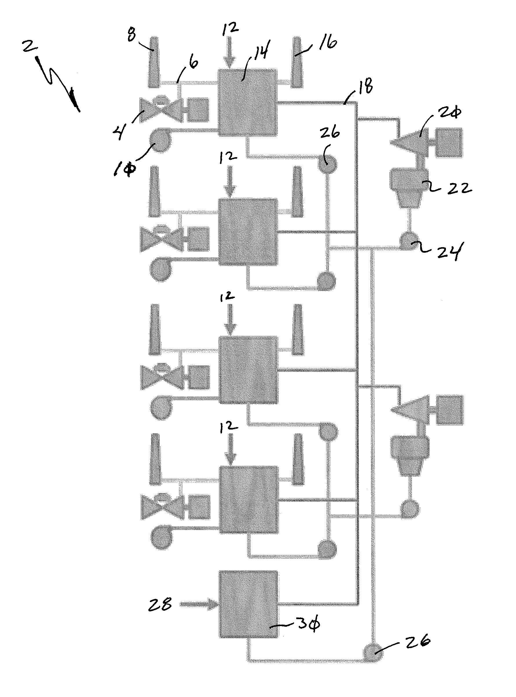
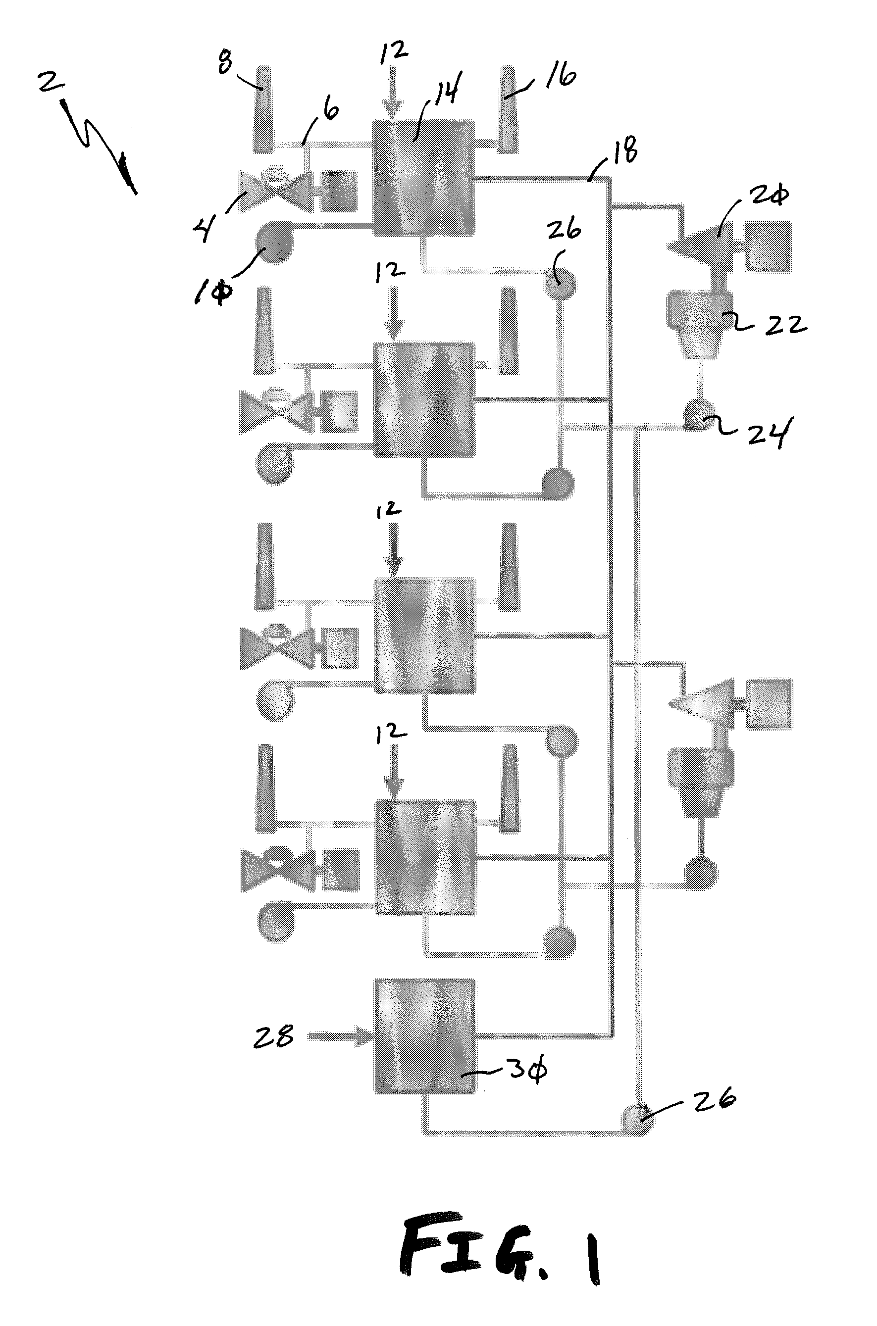
[0031]One embodiment of the present invention is an energy balancing system that possesses fast dispatch time of gas fired simple cycle combustion turbines with the efficiency of a combined cycle system. Once the system is operating, it has the immediate capacity (i.e. spinning reserve) to respond to both up and down capacity requirements with enough flexibility to closely match the variations in wind generated power across a range of dispatch levels from minimum generation up to maximum generation. The variable output of this system will allow for more accurate dispatch orders because any capacity can be delivered (within the designed capacity range of the specific equipment configuration) instead of the “block” dispatch that results from only being able to turn simple cycle combustion turbines either off or on. To achieve this “flexible spinning reserve”, a hybrid configuration of multiple trains of equipment, with certain systems interconnected between the trains, will be require...


PUM


Abstract

An energy balancing system is provided that ensures continuous energy output to compensate for energy fluctuations commonly associated with wind power generation. The flexible energy balancing system employs a base load high-pressure steam boiler that is associated with one or more steam turbine generators. The steam turbine generators are also associated with one or more heat recovery steam generators whose temperature is controlled by the exhaust from combustion turbine generators and the base load high-pressure steam boiler. The energy balancing system can be selectively tuned to quickly compensate for energy fluctuations associated with wind power generation.

Description

[0001]This application claims benefit of U.S. Provisional Patent Application Ser. No. 61 / 554,475, filed Nov. 1, 2011, the entire disclosure of which is incorporated by reference herein.FIELD OF THE INVENTION[0002]Embodiments of the present invention generally relate to a flexible spinning reserve for an energy balancing system used to ensure continuous energy output for intermittent power generation. More specifically, one embodiment of the present invention is a continuously running auxiliary power source associated with a wind power generating facility that rapidly and selectively changes the amount of power delivered to a power grid to supplement wind turbine power generation, which increases and decreases with changes in wind velocity and conditions, to deliver a steady total amount of electrical energy.BACKGROUND OF THE INVENTION[0003]Many states have adopted Renewable Portfolio Standards (RPS) that require electric utility companies to include a minimum amount of renewable ene...

Claims


Application Information

Patent Timeline
Patent Type & Authority Applications(United States)
IPC IPC(8): F02C6/00
CPCF02C6/00F01K23/10F02C6/18F01K3/02F01K7/16F01K7/165F01K23/18
Inventor MARLEY, II, PAUL C.
Why Eureka
Try Eureka