
System, Method and Computer Program Product for Determining Load Profiles

a load profile and computer program technology, applied in the field of system and method for determining the load profile of power line conductors, can solve the problems of power outages, substantial time loss in identifying fault locations,

Inactive Publication Date: 2013-05-02
CURRENT TECH INT
View PDF3 Cites 45 Cited by
  • Summary
  • Abstract
  • Description
  • Claims
  • Application Information

AI Technical Summary

Benefits of technology

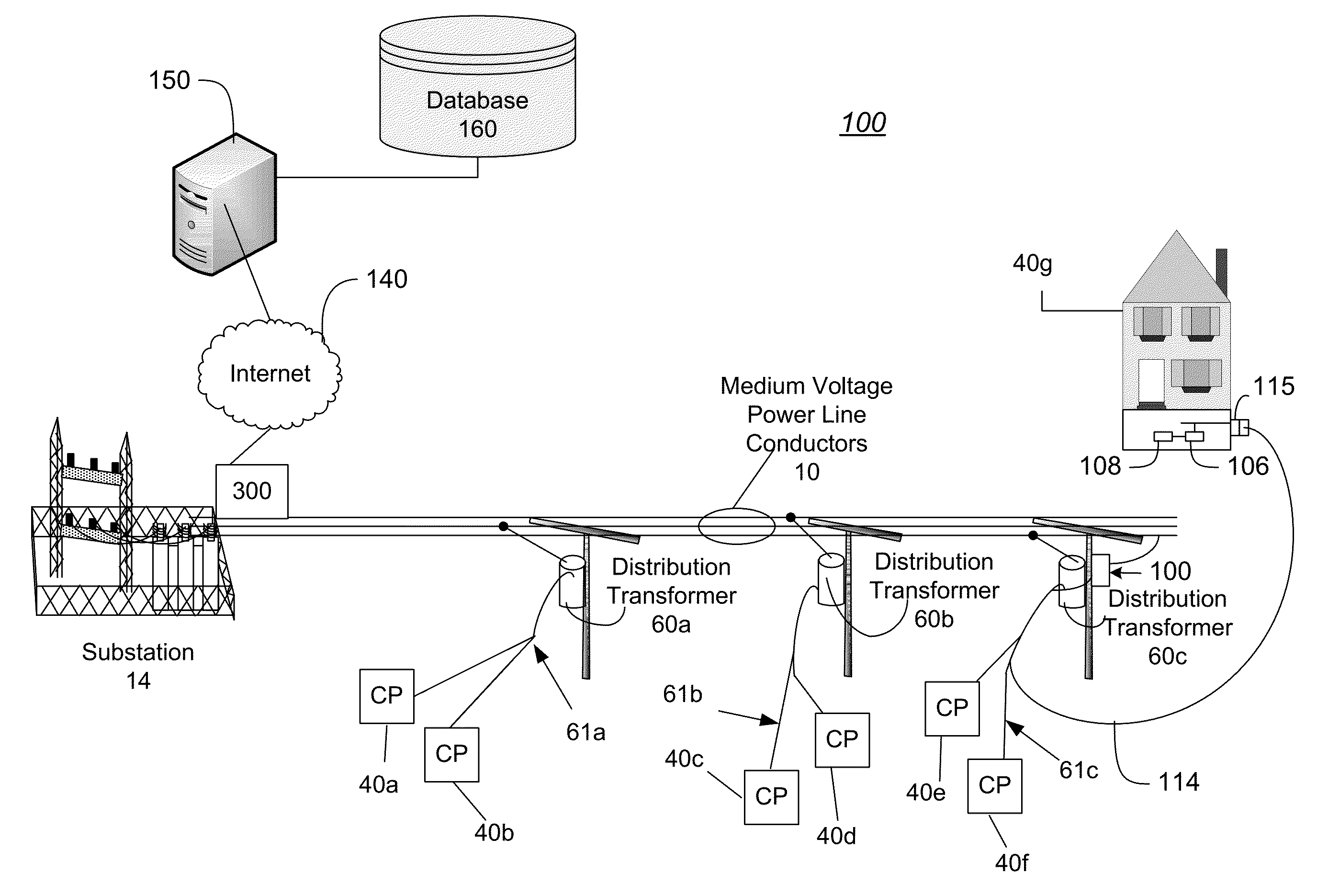
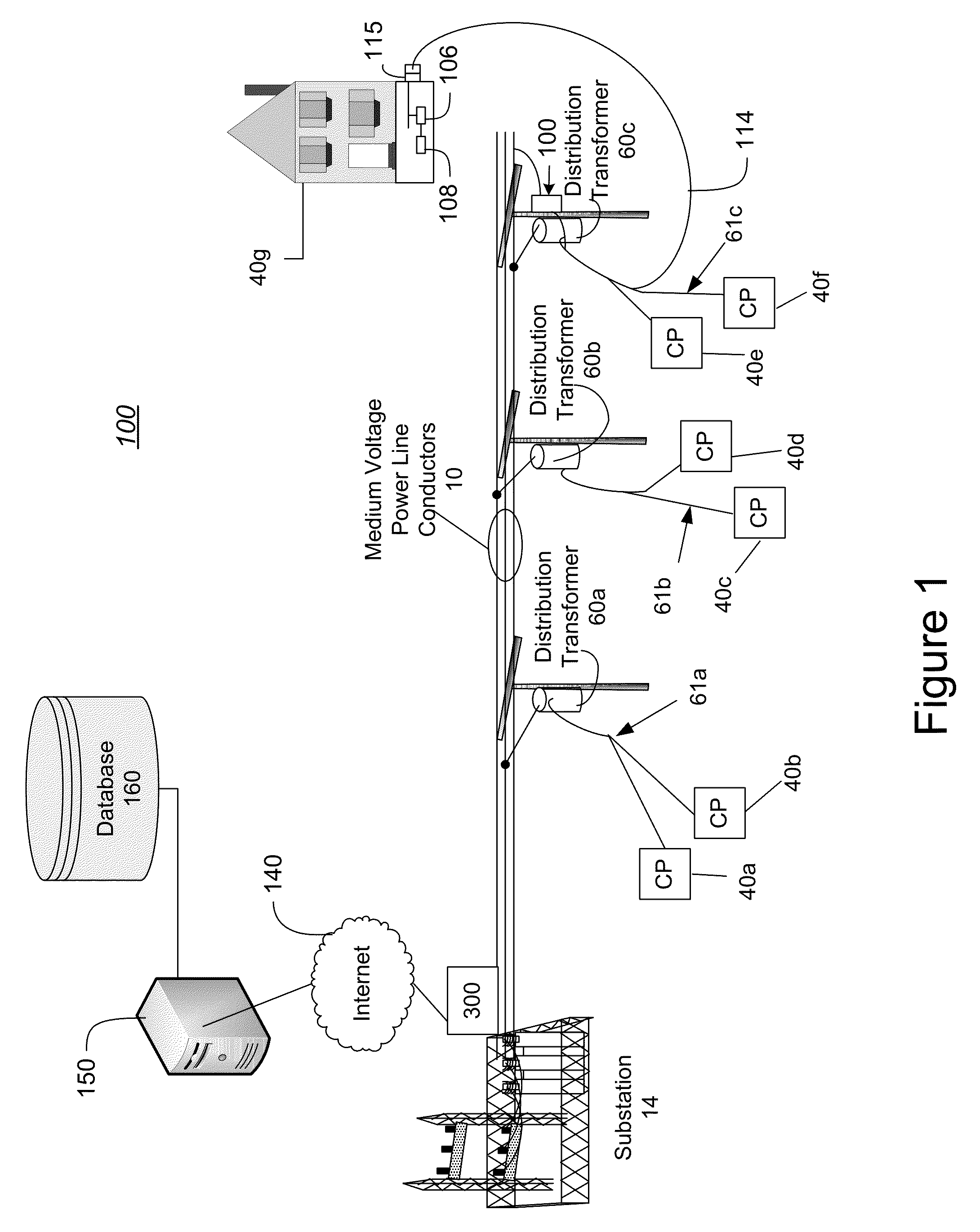
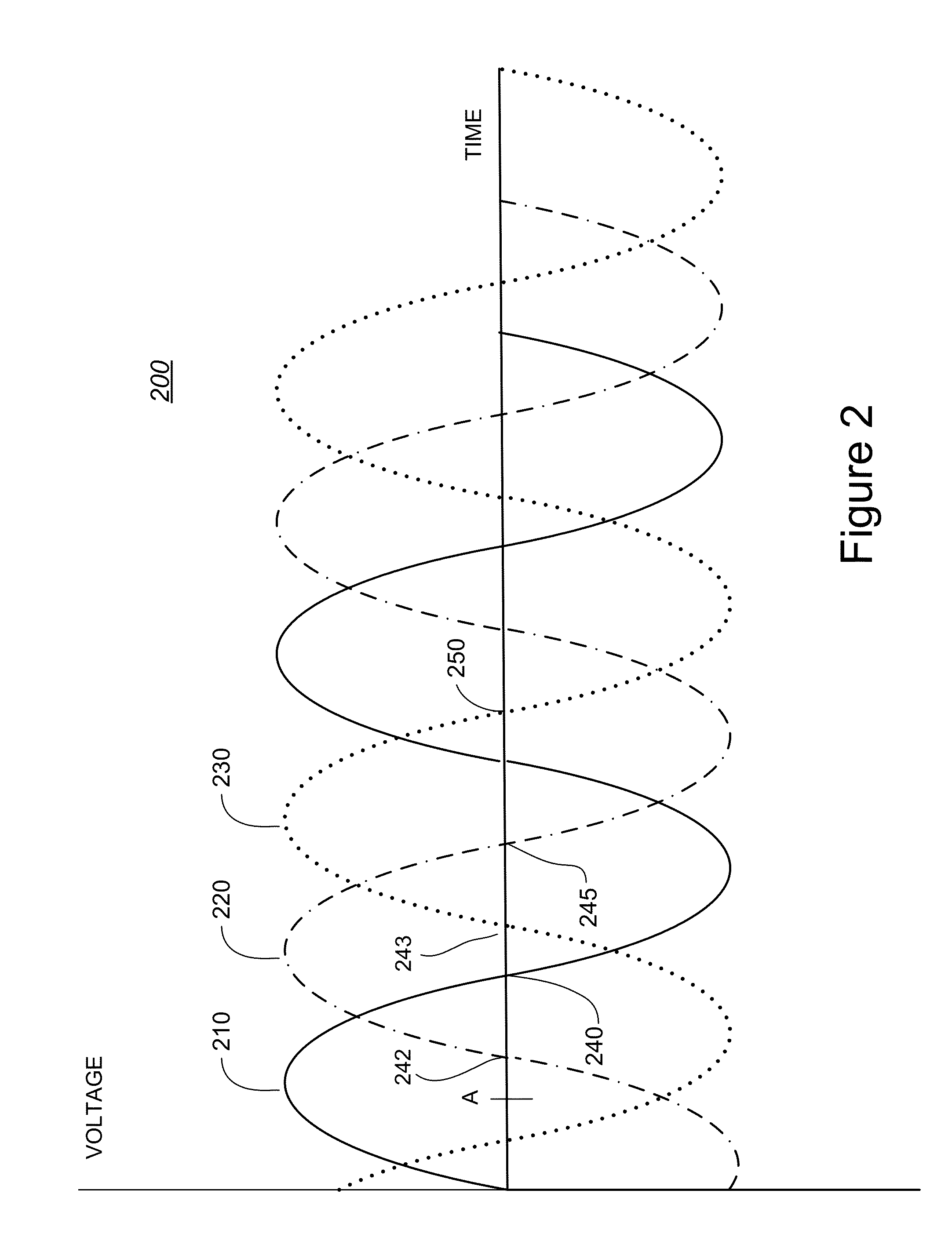
The present invention is a system and method for identifying which phase conductor a target device is connected in a power distribution system. This is useful for maintenance and load balancing purposes. The invention uses a phase identifier message that is transmitted at the zero crossing of the voltage of a first phase conductor. The system includes a network of power lines and devices, and the invention helps to quickly identify which device is connected to which phase conductor, which can save time and improve efficiency in identifying and resolving power outages. The invention can also be used for load balancing and other tasks by using data on the load profiles of power lines.

Problems solved by technology

Even with such maintenance, however, faults occasionally occur, which typically results in a power outage thereby preventing power delivery.
Power outages also may occur due to other events, such as when inclement weather conditions or falling tree branches knock down power lines.
Statistics show that during faults in the power grid, substantial time is lost in identifying fault location.

Method used


Image

  • System, Method and Computer Program Product for Determining Load Profiles
  • System, Method and Computer Program Product for Determining Load Profiles
  • System, Method and Computer Program Product for Determining Load Profiles

Examples


Embodiment Construction

[0014]In the following description, for purposes of explanation and not limitation, specific details are set forth, such as particular networks, communication systems, computers, terminals, devices, components, techniques, data and network protocols, software products and systems, operating systems, development interfaces, hardware, etc. in order to provide a thorough understanding of the present invention.

[0015]However, it will be apparent to one skilled in the art that the present invention may be practiced in other embodiments that depart from these specific details. Detailed descriptions of well-known networks, communication systems, computers, terminals, devices, components, techniques, data and network protocols, software products and systems, operating systems, development interfaces, and hardware are omitted so as not to obscure the description.

[0016]The present invention is directed to a system and method for determining to which phase conductor a target device is connected...


PUM


Abstract

A system, method and device for determining load profile of a power line conductor supplying power to a plurality of power customers is provided. In one embodiment the system comprises an automated meter reading system configured to receive meter data comprising data of the power consumed by each of the plurality of power customers as measured by the power meters; a phase detection system configured to determine one of the plurality of power lines to which each of the power meters is electrically connected; a meter grouping system configured to determine groups of power meter that are commonly connected to the plurality of power line conductors; and a load profile system configured to determine a load profile for each group of power meters by combining the meter data from each meter of each group over a plurality of time periods.

Description

FIELD OF THE INVENTION[0001]The present invention generally relates to a system and method for determining the load profiles of power line conductors and portions of such conductors.BACKGROUND OF THE INVENTION[0002]Electrical power for consumption at residences, offices and other structures is delivered by a power distribution system. The power distribution system (or power grid) typically includes multiple phases and uses a different power line conductor (sometimes referred to herein as phase conductor) to deliver each phase of power. Further, a power distribution system may include numerous sections, which transmit power at different voltages. A section of high voltage power transmission lines forms a power distribution grid for transmitting power from a power plant to substations near populated areas. Various medium voltage (MV) power sections are coupled to the power grid via substations to serve specific regions. An MV power section includes medium voltage power lines carrying ...

Claims


Application Information

Patent Timeline
Patent Type & Authority Applications(United States)
IPC IPC(8): G06F19/00G01R21/133
CPCG01R19/2513G01R29/16G01R29/18H02J13/0079Y04S20/38H02J3/26Y02E40/50H02J2310/70H02J13/00017H02J13/00028H02J13/00034Y04S40/124Y02E60/00G01D2204/24Y04S20/30
Inventor SHARMA, MANULARS, ANDERSSON
Owner CURRENT TECH INT
Learn More