
System and Method for Determining Fluid Speed

a fluid speed and fluid technology, applied in the direction of measuring devices, volume/mass flow by dynamic fluid flow effect, instruments, etc., can solve the problems of degrading or destroying the effectiveness or accuracy of sensors, inaccurate, and affecting the operation of sensors

Active Publication Date: 2013-05-09
TAO OF SYST INTEGRATION
View PDF11 Cites 0 Cited by
  • Summary
  • Abstract
  • Description
  • Claims
  • Application Information

AI Technical Summary

Benefits of technology

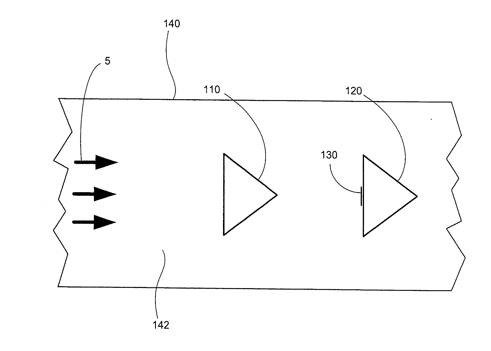
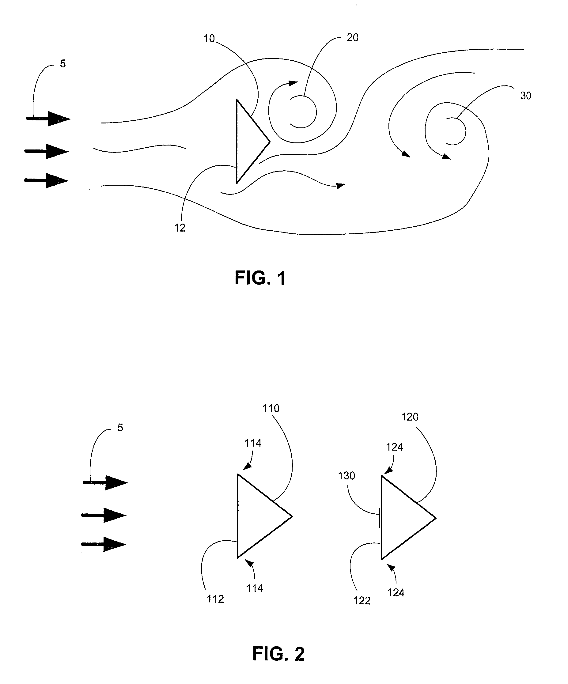
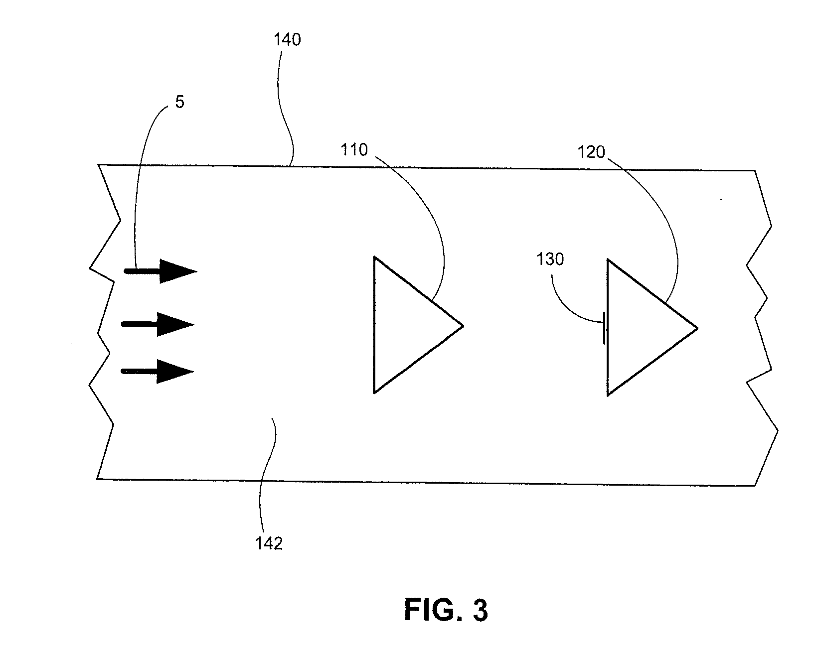
The invention provides a way to measure the speed at which a fluid flows past an object. It uses two obstructive bodies that are placed in front of the fluid stream. The first body creates a barrier in front of the fluid, while the second body creates a barrier behind the object. The resulting changes in fluid flow create periodic vortices that are measured using a sensor. By measuring these vortices, the invention can determine the speed at which the fluid is flowing. This technology can be used in a variety of applications, such as measuring flow in a pipe or detecting currents in oceanic currents.

Problems solved by technology

The effects of foreign objects on sensors and other equipment is typically referred to “foreign object damage,” or “FOD.” FOD can render such sensors inoperative or, potentially worse, inaccurate.
Such exposure, by necessity, results in exposing these elements to solid or liquid materials borne by the fluid.
FOD can result due to impact, erosion, or material build-up, any of which can degrade or destroy the effectiveness or accuracy of the sensors.

Method used


Image

  • System and Method for Determining Fluid Speed
  • System and Method for Determining Fluid Speed
  • System and Method for Determining Fluid Speed

Examples


Embodiment Construction

[0019]While the invention will be described in connection with particular embodiments, it will be understood that the invention is not limited to these embodiments. On the contrary, it is contemplated that various alternatives, modifications and equivalents are included within the spirit and scope of the invention as described.

[0020]The present invention encompasses methods and systems for determining relative fluid flow speed through the use of a sensor device in which the sensor elements are protected from direct impact of foreign material present in the oncoming flow. By avoiding direct impact by such foreign material, the sensor device operates without loss of measurement accuracy and sensitivity.

[0021]As will be discussed in more detail hereafter, a typical embodiment of the invention provides a method of measuring flow speed that involves locating a second obstacle in tandem behind a first obstacle and measuring the shedding frequency with a sensor element embedded on the seco...


PUM


Abstract

A flow speed sensor arrangement is provided for measuring a flow speed of a fluid stream relative to an object. The arrangement comprises a first obstructive body having a first forward facing surface and two lateral edges and a second obstructive body having a second forward facing surface. The second obstructive body is positioned in tandem relative to the first obstructive body so that the first and second forward facing surfaces face the same direction and so that when the first forward facing surface is presented to an incoming fluid stream, the first obstructive body is between the incoming fluid flow and the second obstructive body. A sensor array is disposed on the second forward facing surface. The first and second obstructive bodies are attachable to the object so that the first forward face is presented to an incoming fluid stream when the object is immersed in the fluid stream.

Description

CROSS-REFERENCE TO RELATED APPLICATIONS[0001]This application claims priority to U.S. Provisional Application No. 61 / 555,598 filed Nov. 4, 2011, which is incorporated herein by reference in its entirety.BACKGROUND OF THE INVENTION[0002]This application relates generally to fluid speed measurement and, more particularly, to a device for measuring the relative speed between a body and a fluid by measuring the shedding frequency from an obstacle placed in the flow. Particular applications of the device include the measurement of airspeed in flight vehicles and the measurement of the relative speed of hydrocraft through water.[0003]Relative fluid speed measurements are required for aerodynamic and hydrodynamic control and, in the case of aircraft, for providing indicated airspeeds for stall speeds, landing speeds, never-exceed speeds, and true airspeeds for navigation, weapons release ballistics and a variety of other uses. Typically, aircraft speed is measured by pitot-static systems w...

Claims


Application Information

Patent Timeline
IPC IPC(8): G01F1/32G01F1/00
CPCG01P5/01G01F1/3272G01F1/3273
Inventor MANGALAM, SIVA M.MANGALAM, ARUN
Owner TAO OF SYST INTEGRATION
Learn More