
Method And Apparatus For Ordering Code Candidates In Image For Decoding Attempts

a code candidate and image technology, applied in the field of code readers, can solve the problems of complex algorithms that often require a greater amount of processing power and a corresponding greater amount of time to perform, and the simple decoding algorithm will not be able to successfully decode codes in images,

Active Publication Date: 2013-05-09
COGNEX CORP
View PDF4 Cites 31 Cited by
  • Summary
  • Abstract
  • Description
  • Claims
  • Application Information

AI Technical Summary

Benefits of technology

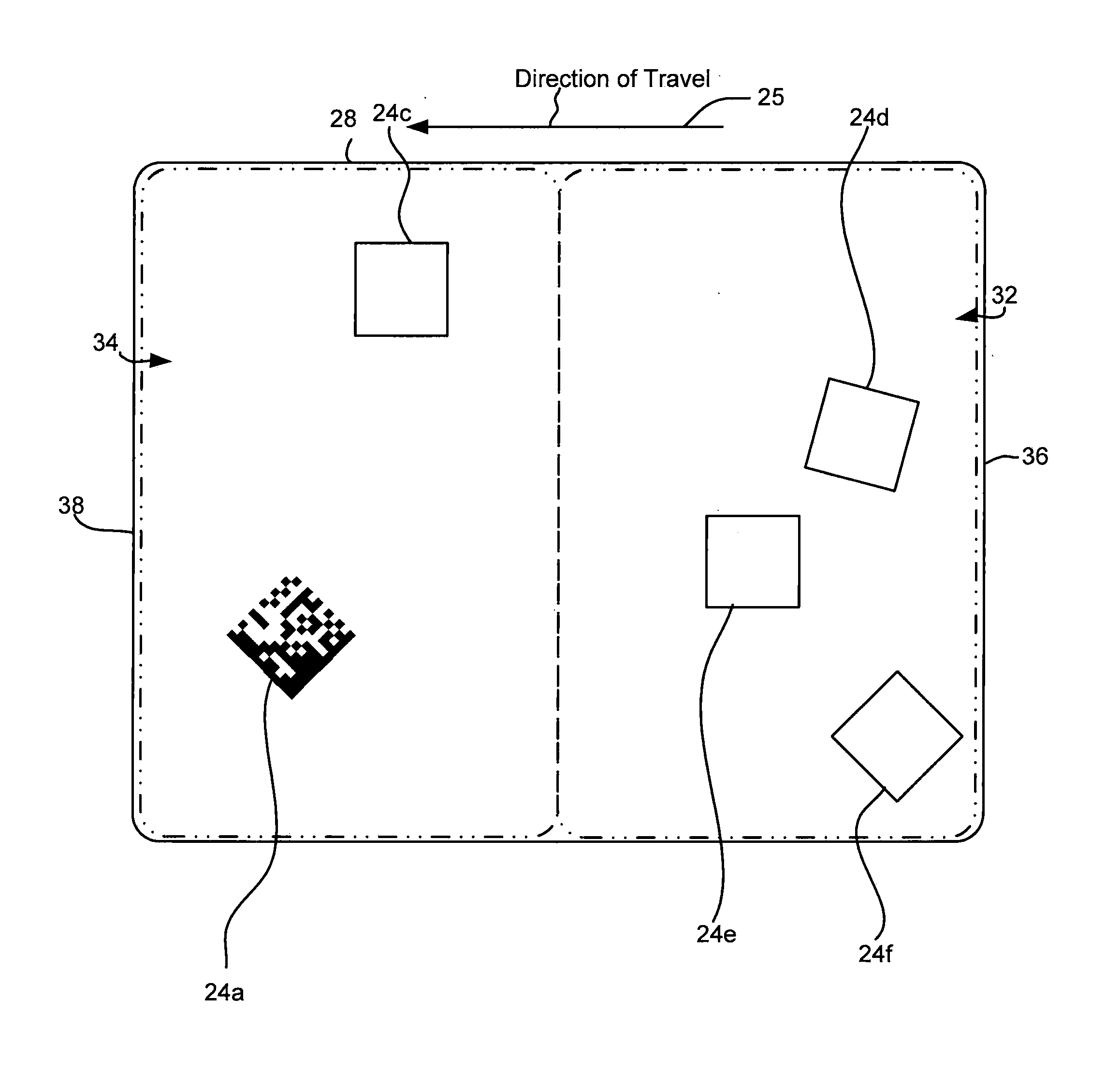
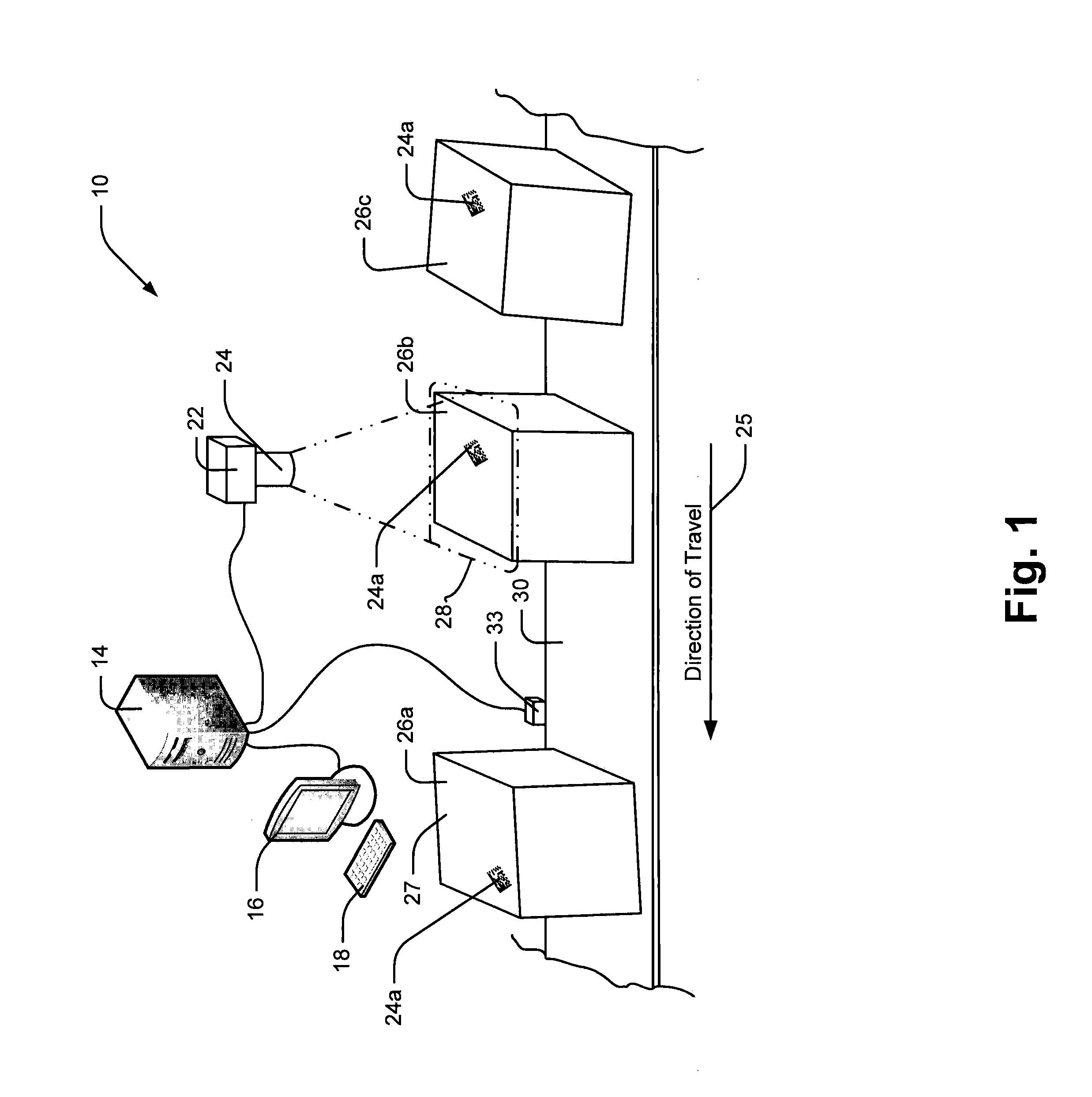
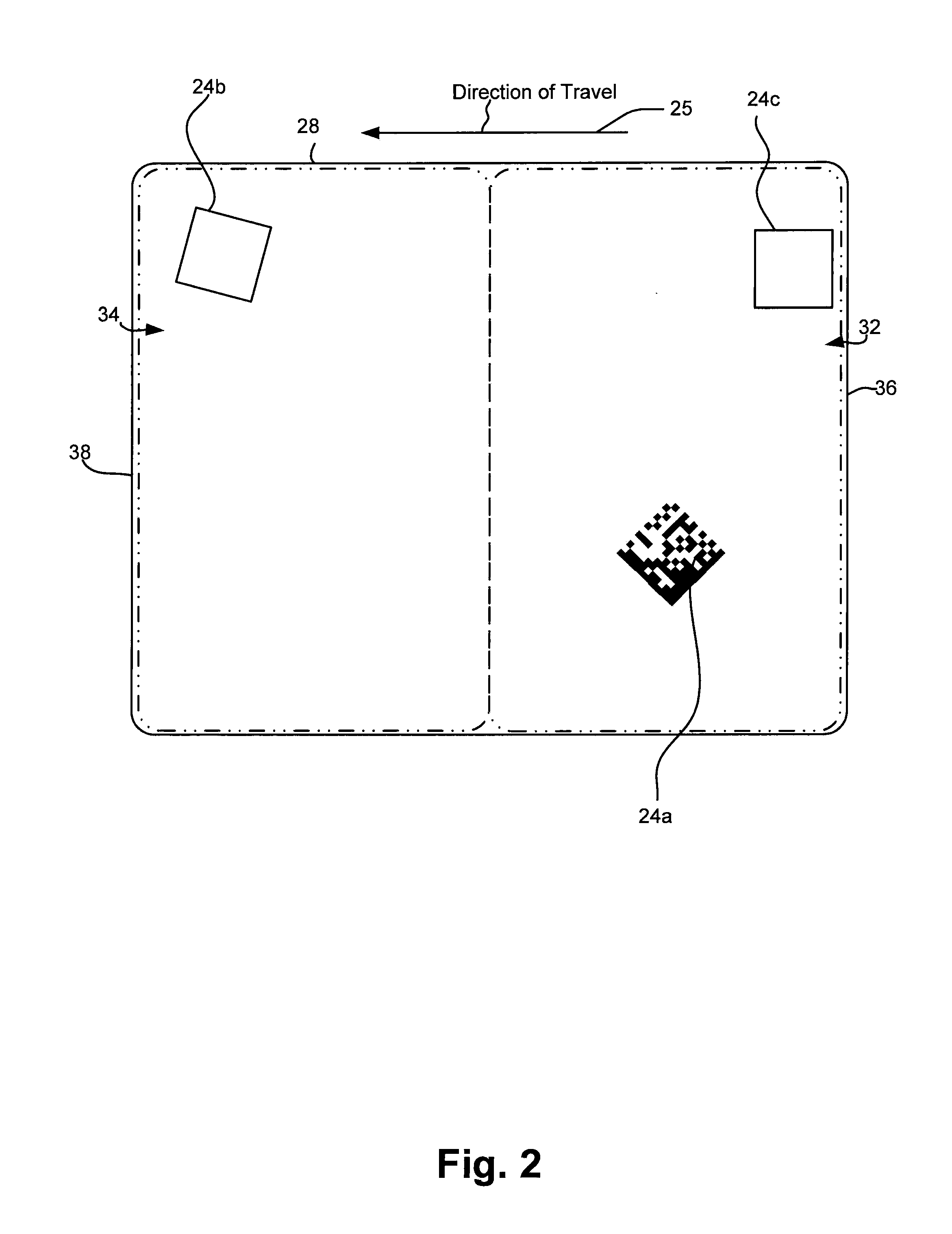
The patent describes a method for decoding codes applied to objects using a camera and a conveyor system. The method involves obtaining images of the code, identifying code candidates in the images, and ordering the code candidates in a specific order based on factors such as the direction of travel through the field of view and the likelihood of the code to be decoded in a future image. The method can be used to efficiently decode code in images and improve the speed and accuracy of the decoding process.

Problems solved by technology

For example, in many cases a simple decoding algorithm will not be able to successfully decode codes in an image unless the circumstances surrounding image acquisition are substantially ideal.
While complex decode algorithms work well to compensate for imperfect images, one draw back is that complex algorithms often require a greater amount of processing power and a commensurate greater amount of time to perform.
While more expensive algorithms are not an issue in some applications, in applications where images are obtained in rapid succession, expensive algorithms requiring long periods to complete can result in computational requirements that far exceed capabilities of reader processors.
More specifically, in some cases, image sensors are capable of obtaining and providing images so quickly that a reader device processor cannot perform a complex algorithm on all code candidates in an image prior to receiving a next image.
In this case, the end result may be that some codes that pass through a field of view are never successfully decoded.

Method used


Image

  • Method And Apparatus For Ordering Code Candidates In Image For Decoding Attempts
  • Method And Apparatus For Ordering Code Candidates In Image For Decoding Attempts
  • Method And Apparatus For Ordering Code Candidates In Image For Decoding Attempts

Examples


Embodiment Construction

[0041]The various aspects of the subject invention are now described with reference to the annexed drawings, wherein like reference numerals correspond to similar elements throughout the several views. It should be understood, however, that the drawings and detailed description hereafter relating thereto are not intended to limit the claimed subject matter to the particular form disclosed. Rather, the intention is to cover all modifications, equivalents, and alternatives falling within the spirit and scope of the claimed subject matter.

[0042]As used herein, the terms “component,”“system” and the like are intended to refer to a computer-related entity, either hardware, a combination of hardware and software, software, or software in execution. For example, a component may be, but is not limited to being, a process running on a processor, a processor, an object, an executable, a thread of execution, a program, and / or a computer. By way of illustration, both an application running on a...


PUM


Abstract

A method and apparatus for decoding codes applied to objects for use with a camera and a conveyor system wherein the camera includes an image sensor having a two dimensional field of view (FOV), the method comprising the steps of providing a processor programmed to perform the steps of obtaining images of the FOV, for each image identifying code candidates in at least portions of the image, ordering at least a subset of the code candidates for decoding in a candidate order wherein the candidate order is determined at least in part as a function of a first direction of travel through the FOV, attempting to decode code candidates in the order specified by the direction of travel and when a new image event occurs, foregoing attempts to decode at least a portion of the identified code candidates.

Description

CROSS-REFERENCE TO RELATED APPLICATIONS[0001]Not applicable.STATEMENT REGARDING FEDERALLY SPONSORED RESEARCH OR DEVELOPMENT[0002]Not applicable.BACKGROUND OF THE INVENTION[0003]The present invention relates to code readers and more specifically to code readers that attempt to optimize decode processes to decode code candidates in a rapid succession of obtained images.[0004]Automated identification of products using optical codes has been broadly implemented throughout industrial operations and in many other applications for many years. Optical codes are patterns composed of elements with different light reflectance or emission, assembled in accordance with predefined rules. The elements in the optical codes may be bars or spaces in a linear barcode, or the on / off pattern in a two-dimensional matrix code. The bar code or symbols can be printed on labels placed on product packaging, or directly on the product itself by direct part marking. The information encoded in a bar code or symb...

Claims


Application Information

Patent Timeline
Patent Type & Authority Applications(United States)
IPC IPC(8): G06K7/10
CPCG06K7/10871G06K7/1443G06K7/1465G06K7/10762G06K7/1417G06K7/10722
Inventor NEGRO, JAMESKEATING, JOHN F.MOED, MICHAEL C.
Owner COGNEX CORP
Learn More