Antenna Fixing Unit

a technology for fixing units and antennas, which is applied in the direction of fishing, machine supports, other domestic objects, etc., can solve the problems of limiting the tightening force that can be exerted on the roof, limiting the tightening force, and not allowing the antenna to be effectively fixed to the roof, so as to reduce the complexity of the fixing unit, reduce the risk of spontaneous loosening of the screw, and reduce the assembly time of the fixing unit

Active Publication Date: 2013-05-09
CALEARO ANTENNE SRL
View PDF8 Cites 10 Cited by
  • Summary
  • Abstract
  • Description
  • Claims
  • Application Information

AI Technical Summary

Benefits of technology

[0020]Advantageously, the lower number of components makes it possible to reduce the complexity of the fixing unit and therefore its cost compared to the fixing units of known type.
[0021]Still advantageously, the lower number of components makes it poss

Problems solved by technology

However, the known fixing body described above poses the drawback that the fixing element alone does not allow the antenna to be effectively fixed to the roof.
In fact, the deformability of the projecting bodies, which allows them to be moved near each other and then parted, limits the tightening force that can be exerted on the roof by the projecting bodies.
A further drawback due to said deformability lies in that the projecting bodies tend to part excessively during tightening, thus further limiting the tightening force.
Howe

Method used


Image

  • Antenna Fixing Unit
  • Antenna Fixing Unit
  • Antenna Fixing Unit

Examples


Embodiment Construction

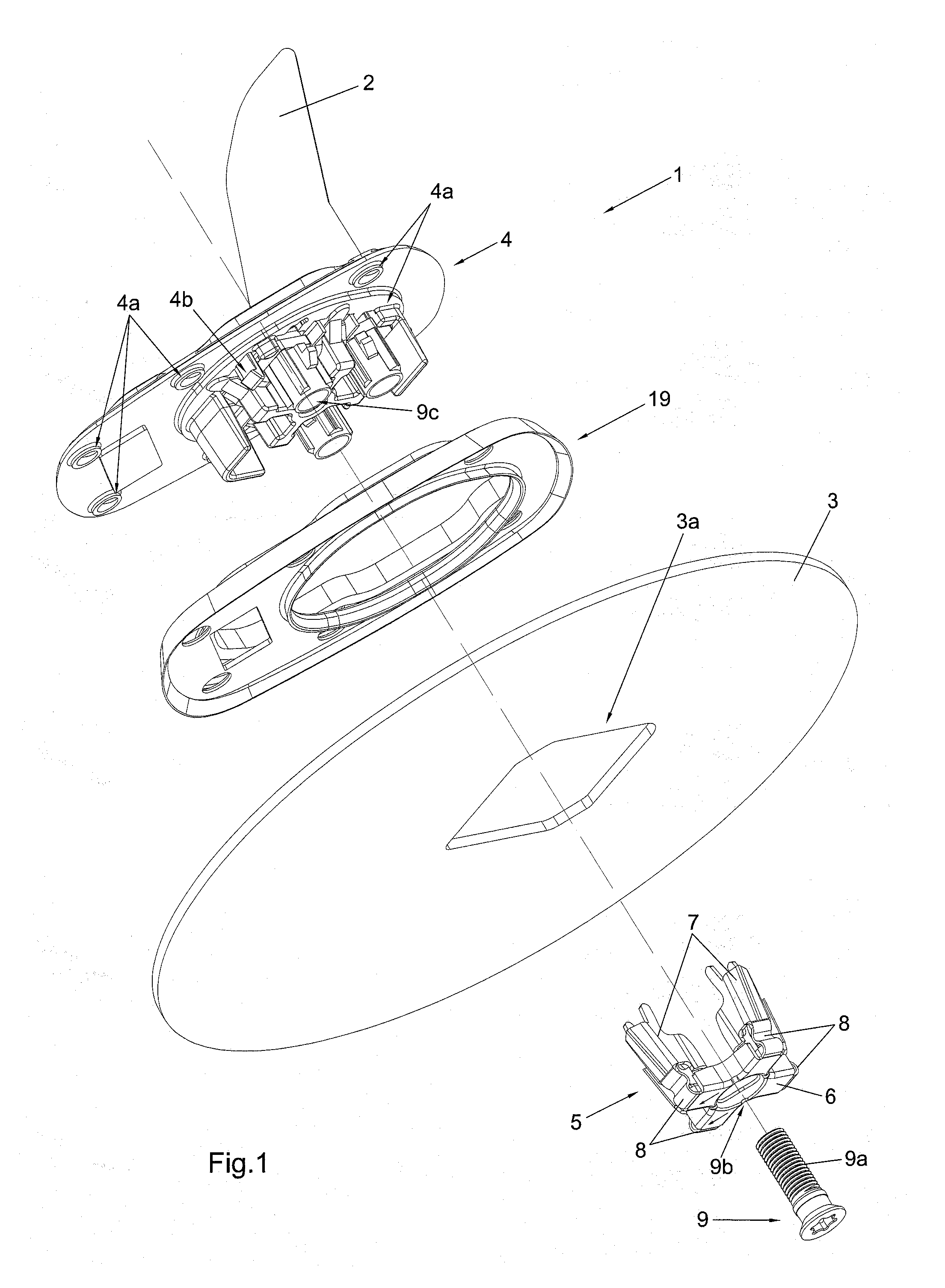
[0028]The fixing unit of the invention, shown in FIG. 1 and indicated as a whole by 1, is particularly suited to be used to fix an antenna 2 to a plate-like supporting body 3 like, for example, the roof of a vehicle, on which a through hole 3a has been previously made.

[0029]As shown in the figure, the fixing unit 1 comprises a base element 4 that supports an antenna 2 of the type known per se and is provided with a contact surface 4a suited to be arranged so that it rests on the plate-like supporting body 3.

[0030]The contact surface 4a is preferably but not necessarily defined by a plurality of projecting areas spaced from one another that advantageously allow the contact surface 4a to effectively rest on plate-like supporting bodies featuring different curvatures.

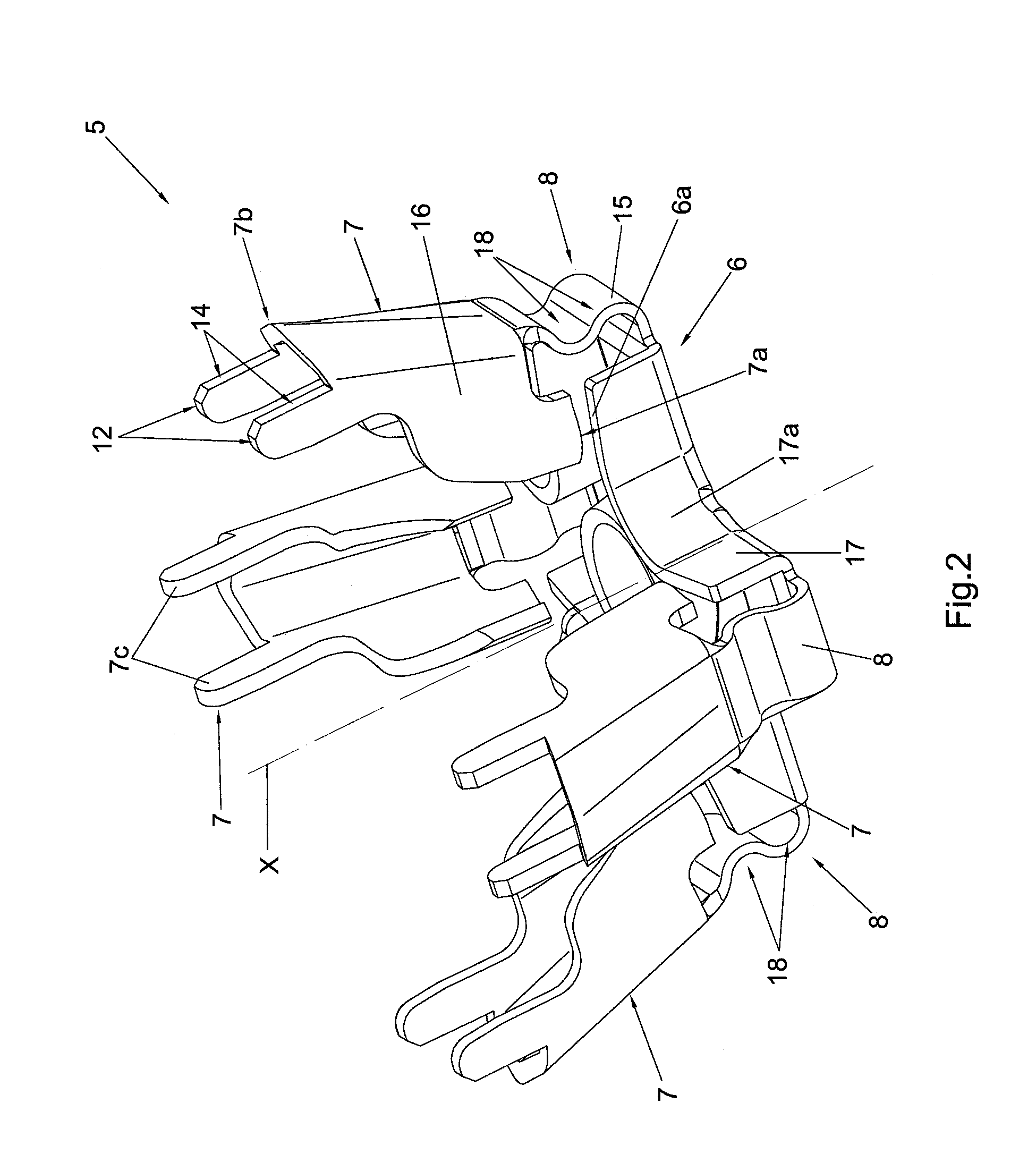
[0031]The fixing unit 1 also comprises a fixing element 5 that can be connected to the base element 4 through the hole 3a so that it can be arranged on the opposite side of the plate-like supporting body 3.

[0032]In particu...


PUM


Abstract

The invention is a unit for fixing an antenna, comprising: a base element suited to support the antenna, provided with a contact surface suited to rest against a plate-like supporting body; a fixing element comprising a main body suited to be connected to the base element through joining means that define a connection direction, and a projecting body mainly developed according to the connection direction and associated with the main body through a deformable connection section. The projecting body has a reference surface facing a corresponding thrust surface of the main body and spaced from it, the connection section being configured so that its deformation makes it possible to move near each other and bring into contact the reference surface and the thrust surface when the fixing element is connected to the base element.

Description

FIELD OF THE INVENTION[0001]The present invention concerns a unit for fixing an antenna to a plate-like supporting body like, for example, the roof of a vehicle.BACKGROUND OF THE INVENTION[0002]A fixing unit of known type comprises a base element that supports the antenna, provided with a contact surface that is arranged so that it rests on the outside of the vehicle's roof.[0003]A fixing element is also provided, which is connected to the base element through a screw and comprises a plurality of projecting bodies mainly developed according to the connection direction defined by the screw, with the ends slightly parted.[0004]In order to fix the antenna to the roof, the base element and the fixing element are first arranged on opposite sides of the roof at the level of an apposite through hole.[0005]Successively, the screw is screwed so that the ends of the projecting bodies come into contact with the roof.[0006]The above mentioned projecting bodies are elastically deformable so that...

Claims


Application Information

Patent Timeline
IPC IPC(8): H01Q1/12H01Q1/32
CPCH01Q1/1214H01Q1/32H01Q1/12H01Q1/3275
Inventor SPAGNOLO, GIOELEKARCHER, TORSTENSALIN, NATALINOZAMBERLAN, DANIELCIMAN, MASSIMO CALEAROROTONDI, VITO
Owner CALEARO ANTENNE SRL
Why Eureka
Try Eureka