Multi-stage crest factor reduction (CFR) for multi-channel multi-standard radio

a multi-channel, multi-standard radio technology, applied in the field of digital signal processing techniques, can solve the problems of composite signal crest factor reduction on the combined signal at a high sampling rate (with significant complexity), and the efficiency of power amplifiers (pas) employed in wireless base stations is affected, and the technology typically has different latency requirements

Active Publication Date: 2013-05-09
INTEL CORP
View PDF10 Cites 25 Cited by
  • Summary
  • Abstract
  • Description
  • Claims
  • Application Information

AI Technical Summary

Benefits of technology

[0008]Generally, multi-stage crest factor reduction (CFR) techniques are provided for multi-channel multi-standard radio (MSR). According to one aspect of the invention, a multi-stage crest factor reduction method comprises applying one or more data samples associated with at least one channel of a first technology type to a first individual crest factor reduction block; applying one or more data samples associated with at least one channel of a second technology type to a second individual crest factor reduction block; aggregating outputs of the first and second individual crest factor reduction blocks to generate an aggregated output; and applying the aggregated output to a composite crest factor reduction block.

Problems solved by technology

In many wireless communication technologies, the communication signals often have a high peak-to-average ratio (PAR) that can impair the efficiency of the power amplifiers (PAs) employed in wireless base stations.
Thereafter, the resulting composite signal undergoes Crest Factor Reduction on the combined signal at a high sampling rate (with significant complexity).
Thus, the different technologies typically have different latency requirements.

Method used


Image

  • Multi-stage crest factor reduction (CFR) for multi-channel multi-standard radio
  • Multi-stage crest factor reduction (CFR) for multi-channel multi-standard radio
  • Multi-stage crest factor reduction (CFR) for multi-channel multi-standard radio

Examples


Embodiment Construction

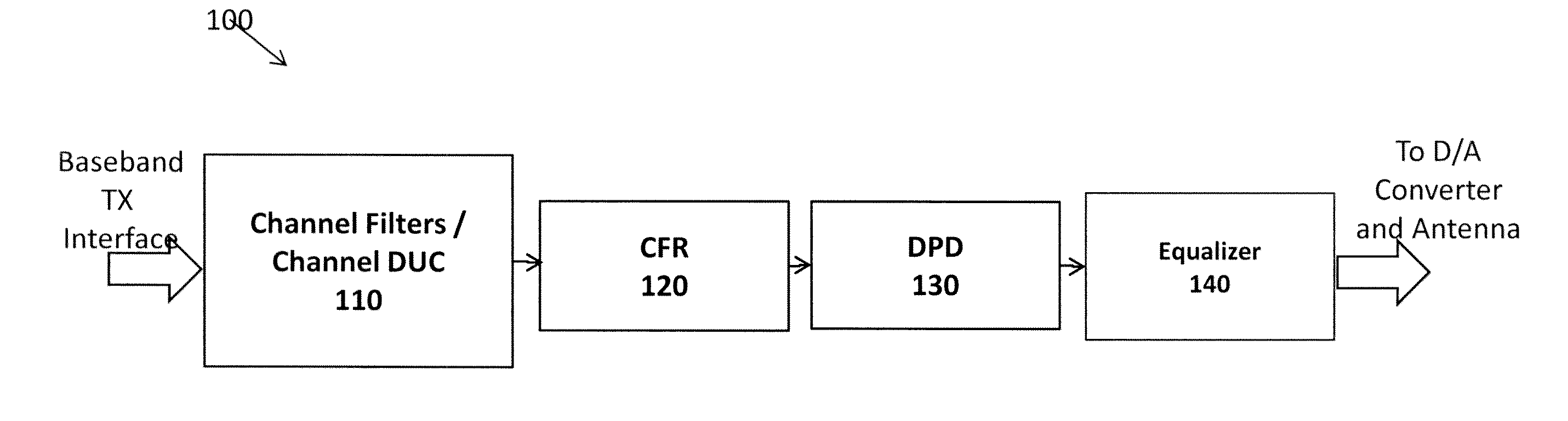
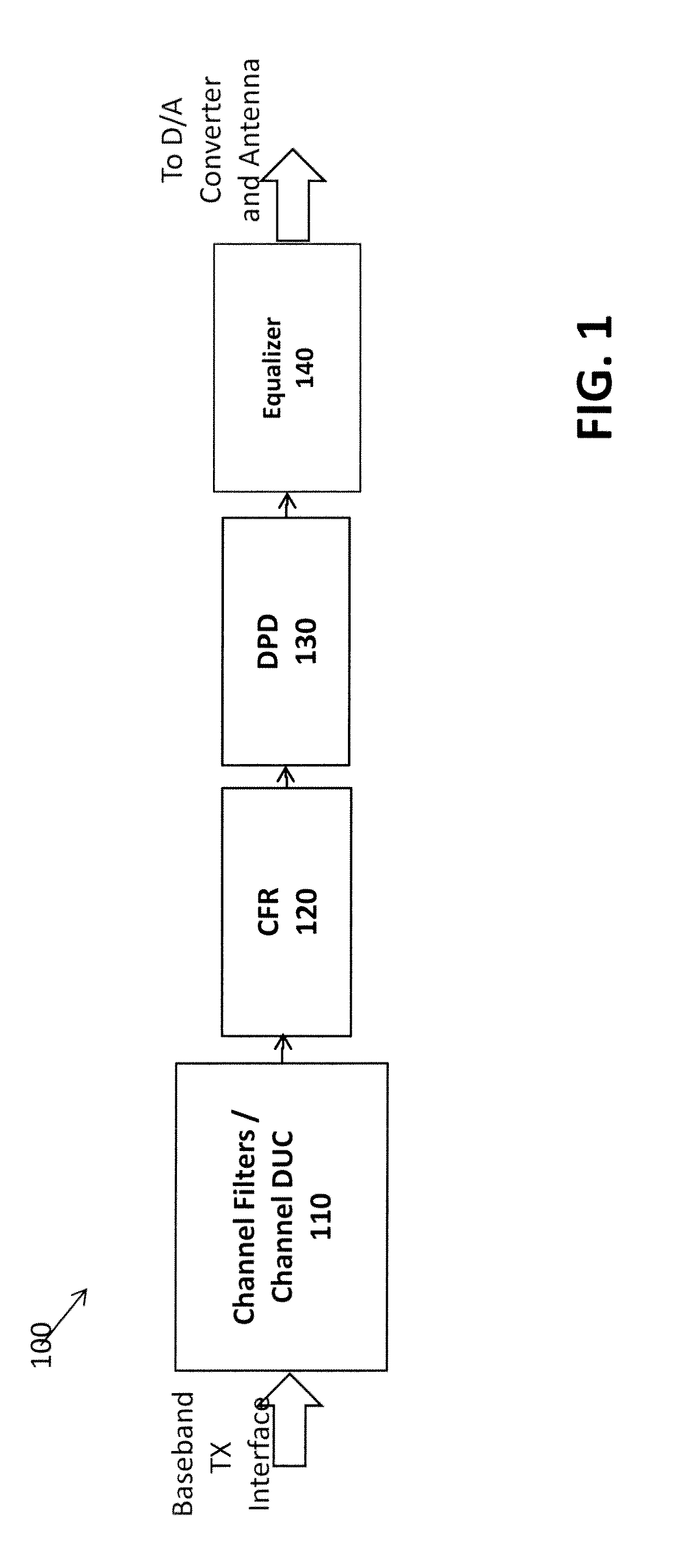
[0015]FIG. 1 illustrates portions of an exemplary transmitter 100 in which aspects of the present invention may be employed. As shown in FIG. 1, the exemplary transmitter portion 100 comprises a channel filter and digital up conversion (DUC) stage 110, a crest factor reduction (CFR) stage 120, a digital pre-distortion (DPD) stage 130 and an optional equalization stage 140. Generally, the channel filter and digital up conversion stage 110 performs channel filtering using, for example finite impulse response (FIR) filters and digital up conversion to convert a digitized baseband signal to an intermediate frequency (IF). As indicated above. the crest factor reduction stage 120 limits the PAR of the transmitted signal. The digital pre-distortion stage 130 linearizes the power amplifier to improve efficiency. The equalization stage 140 employs RF channel equalization to mitigate channel impairments.

[0016]When the transmitter 100 is embodied as a multi-radio, multi-channel system, a base-...


PUM


Abstract

Multi-stage crest factor reduction (CFR) techniques are provided for multi-channel multi-standard radio (MSR). A multi-stage crest factor reduction method comprises applying one or more data samples associated with at least one channel of a first technology type to a first individual crest factor reduction block; applying one or more data samples associated with at least one channel of a second technology type to a second individual crest factor reduction block; aggregating outputs of the first and second individual crest factor reduction blocks to generate an aggregated output; and applying the aggregated output to a composite crest factor reduction block. The individual crest factor reduction blocks can be implemented using a sampling rate appropriate for the corresponding technology type. The composite crest factor reduction block operates at a higher sampling rate than the individual crest factor reduction blocks.

Description

CROSS-REFERENCE TO RELATED APPLICATIONS[0001]The present application claims priority to U.S. Patent Provisional Application Ser. No. 61 / 552,242, filed Oct. 27, 2011, entitled “Software Digital Front End (SoftDFE) Signal Processing and Digital Radio,” incorporated by reference herein.[0002]The present application is related to International Patent Application Serial No. PCT / ______, entitled “Block-Based Crest Factor Reduction (CFR);” and U.S. patent application Ser. No. ______, entitled “Crest Factor Reduction (CFR) Using Asymmetrical Pulses,” each filed contemporaneously herewith and incorporated by reference herein.FIELD OF THE INVENTION[0003]The present invention is related to digital signal processing techniques and, more particularly, to techniques for Crest Factor Reduction.BACKGROUND OF THE INVENTION[0004]The crest factor or peak-to-average ratio (PAR) is a measurement of a waveform, calculated from the peak amplitude of the waveform divided by the RMS value of the waveform. I...

Claims


Application Information

Patent Timeline
Patent Type & Authority Applications(United States)
IPC IPC(8): H04B1/04
CPCH04L1/0054H04B1/0475G06F5/01H04L27/2334H03M3/30G06F9/3001H04L25/02H04L25/03178H04B1/62G06F9/30036H03F1/0288H03F1/3241H03F1/3258H03F3/189H03F3/24H04L25/03216H04L27/2614H03F2201/3233H03F2201/3224H03F2201/3209H03F2201/3212H03F2200/336H04B1/0003G06F9/3895H04B2001/0408H04L27/2623H04L25/03834G06F17/15H03H17/06H04L25/03H04L25/4917
Inventor AZADET, KAMERANMOLINA, ALBERT
Owner INTEL CORP
Why Eureka
Try Eureka