Robot programming device

a programming device and robot technology, applied in the field of robot programming devices, can solve the problems of not taking into account the interference between the robot or the non-processing part of the robot or the tool and the workpiece or the peripheral device at each teaching point, the adjustment work on the three-dimensional space also requires a significant amount of time, and the correction work is significan

Active Publication Date: 2013-05-09
FANUC LTD
View PDF7 Cites 29 Cited by
  • Summary
  • Abstract
  • Description
  • Claims
  • Application Information

AI Technical Summary

Benefits of technology

[0009]To achieve the above object, according to the first mode, a robot programming device is provided that teaches a robot operation program for arranging and displaying three-dimensional models of a robot on which a tool is mounted, a workpiece, and at least one peripheral device, on a screen, at the same time, and for allowing the tool or the robot to avoid interfering with the workpiece or the peripheral device and perform processing work of the workpiece, and this robot programming device includes: a processing line designating unit that designates a processing line on a three-dimensional model of the workpiece; an operation mode designating unit that designates an operation mode, speed, position, and posture of a teaching point that is generated based on the processing line designated by the processing line designating unit; a program generation unit that generates an operation program for the robot based on the processing line that is designated by the processing line designating unit and the operation mode, speed, position, and posture that are designated by the operation mode designating unit; an interference target desig

Problems solved by technology

However, upon generating teaching points on the CAD model of the workpiece, interference between the robot or the tool non-processing part and the workpiece or the peripheral device at each teaching point is not taken into consideration.
Consequently, after generating the

Method used


Image

  • Robot programming device
  • Robot programming device
  • Robot programming device

Examples


first embodiment

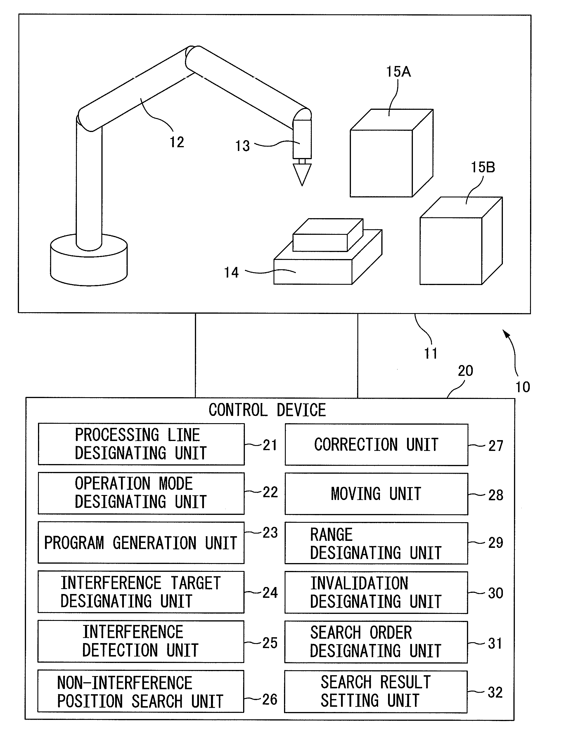
[0034]FIG. 1 is a conceptual diagram of a robot programming device based on the present invention. The robot programming device 10 primarily includes a display unit 11 (for example, a liquid crystal display, a CRT, etc.) and a control device 20 (for example, a digital computer) that is connected to the display unit 11.

[0035]In FIG. 1, the display unit 11 displays a three-dimensional model of a robot 12 (for example, an articulated robot) and a three-dimensional model of a tool 13 that is attached to the tip of the robot 12. The tool 13 varies depending on what work the robot 12 performs (for example, deburring work, arc welding, etc.).

[0036]Furthermore, the display unit 11 also displays a three-dimensional model of a workpiece 14 that is to be processed by the tool 13, and three-dimensional models of peripheral devices 15A and 15B. Note that, in the following, the three-dimensional model of the robot 12 may be simply referred to as “robot 12,” and the same applies to other members a...

second embodiment

[0066]As illustrated in FIG. 12, also with the second embodiment, first, in step S21, three-dimensional models of the robot 12, the tool 13, the workpiece 14 and the peripheral device 15A are displayed on the display unit 11.

[0067]Then, in step S22, the moving unit 28 of the control device 20 (see, for example, FIG. 1) moves the three-dimensional model of the robot 12 to an arbitrary designated position on the display unit 11. Assuming that the designated position is located in a position not contacting the workpiece 14 in the three-dimensional space. As can be seen from FIG. 13, in step S22, the robot 12 is moved as indicated by the curved arrow.

[0068]As explained earlier with reference to FIG. 4A and FIG. 4B, the interference target designating unit 24 applies settings such that the tool processing part 13a of the tool 13 is excluded from the interference target in interference check. Alternately, as illustrated in FIG. 4B, the interference target designating unit 24 may designate...


PUM


Abstract

A robot programming device (10) includes: a processing line designating unit (21) that designates a processing line (41); an operation mode designating unit (22) that designates an operation mode of the teaching point; a program generation unit (23) that generates a program for a robot (12) based on the processing line and the operation mode; an interference target designating unit (24) that designates a tool non-processing part as an interference target; an interference detection unit (25) that detects interference between the robot and the workpiece, at a teaching point; a non-interference position search unit (26) that searches for a non-interference position; and a correction unit (27) that corrects a position of the teaching point based on a search result.

Description

BACKGROUND OF THE INVENTION[0001]1. Technical Field[0002]The present invention relates to a robot programming device that operates offline and teaches a robot operation program for arranging and displaying three-dimensional models of a robot on which a tool is mounted, a workpiece, and at least one peripheral device, on a screen, at the same time, and for allowing the tool or the robot to avoid interfering with the workpiece or the peripheral device, and perform processing work of the workpiece.[0003]2. Description of Related Arts[0004]In recent years, there have been increasing cases of employing an offline programming scheme for teaching operation of a robot. According to this scheme, processing lines, where a workpiece should be processed, are designated on a CAD model of the workpiece, and conditions such as the tool's posture and operation speed are designated, and teaching points are generated. The operator then makes corrections by checking interference between the robot or a...

Claims


Application Information

Patent Timeline
IPC IPC(8): G05B19/04
CPCG05B19/4097B25J9/1671G05B2219/40507G05B2219/40317G05B2219/40107Y02P90/02G05B19/4061
Inventor ATOHIRA, HIROYUKI
Owner FANUC LTD
Why Eureka
Try Eureka