
Seat back frame

Inactive Publication Date: 2013-05-16
TOYOTA BOSHOKU KK
View PDF2 Cites 3 Cited by
  • Summary
  • Abstract
  • Description
  • Claims
  • Application Information

AI Technical Summary

Benefits of technology

The invention is a seat back frame that reduces the vibration of a headrest during normal operation while still supporting the occupant in the event of a collision. The headrest mounting member is designed to only support the headrest at one location during normal operation, which prevents vibration. When a collision occurs, the headrest mounting member automatically changes to support the occupant at another location to ensure their safety. The upper frame member, which the headrest mounting member overlaps, is designed with a pipe-shape to retain its original bending strength and improve support performance. The invention prevents abnormal noise and vibration caused by repeated abutting of the headrest mounting member against the frame.

Problems solved by technology

However, the resonance frequency of the headrest (i.e., of the resonance with respect to the seat back frame) increases to close to the resonance point of the floor panel described above, so the headrest will end up amplifying the vibration level of the floor panel and vibrating, which is problematic.
That is, increasing the support performance for an occupant when a collision occurs and suppressing vibration of the headrest are technologically contradictive tasks as long as the support rigidity of the headrest mounting member is simply adjusted (i.e., increased and decreased).
It is also possible to reduce the resonance frequency of the headrest by increasing the mass of the headrest, but this would result in a corresponding increase in both vehicle mass and cost, which is undesirable.

Method used


Image

  • Seat back frame
  • Seat back frame
  • Seat back frame

Examples


Embodiment Construction

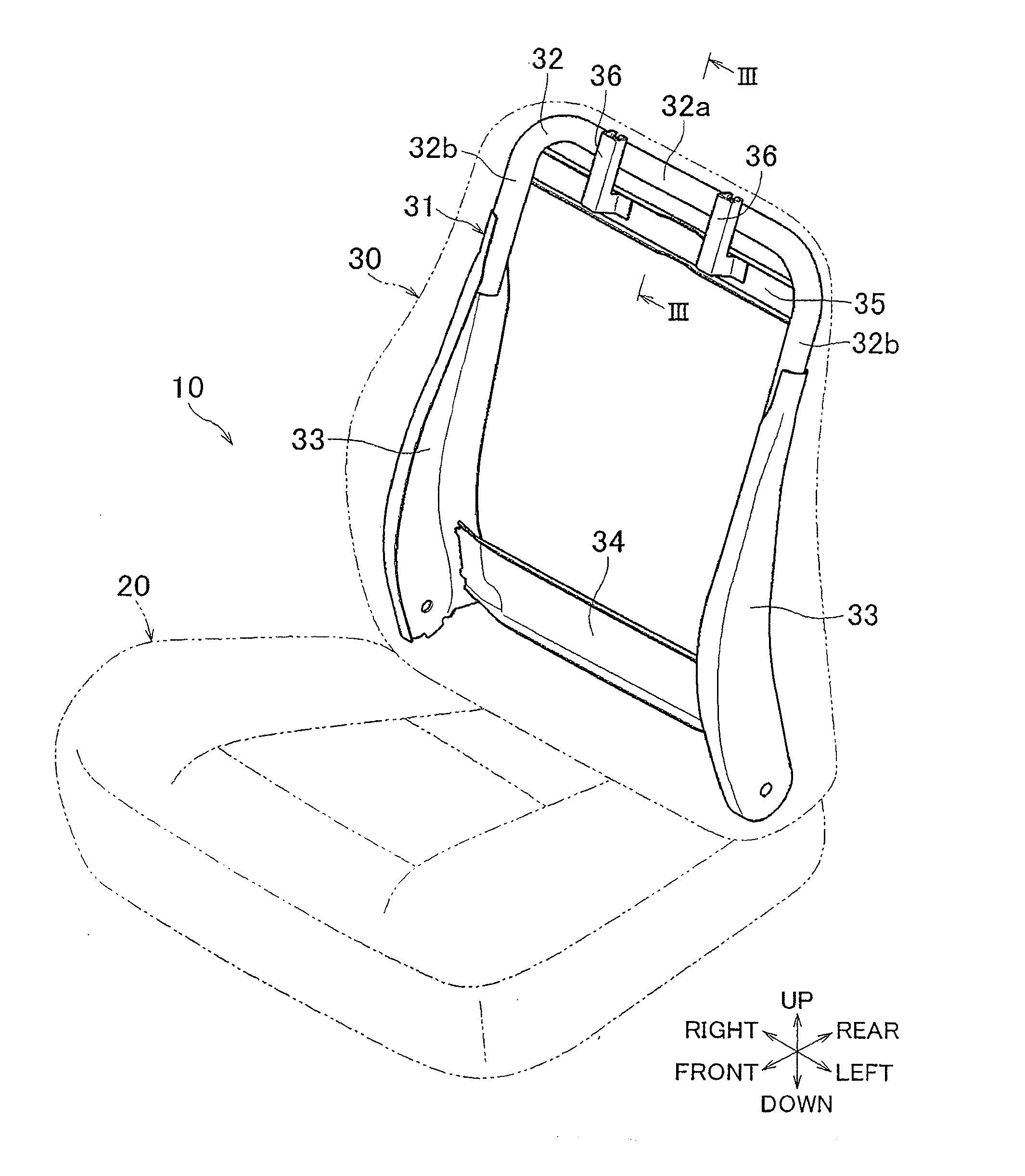
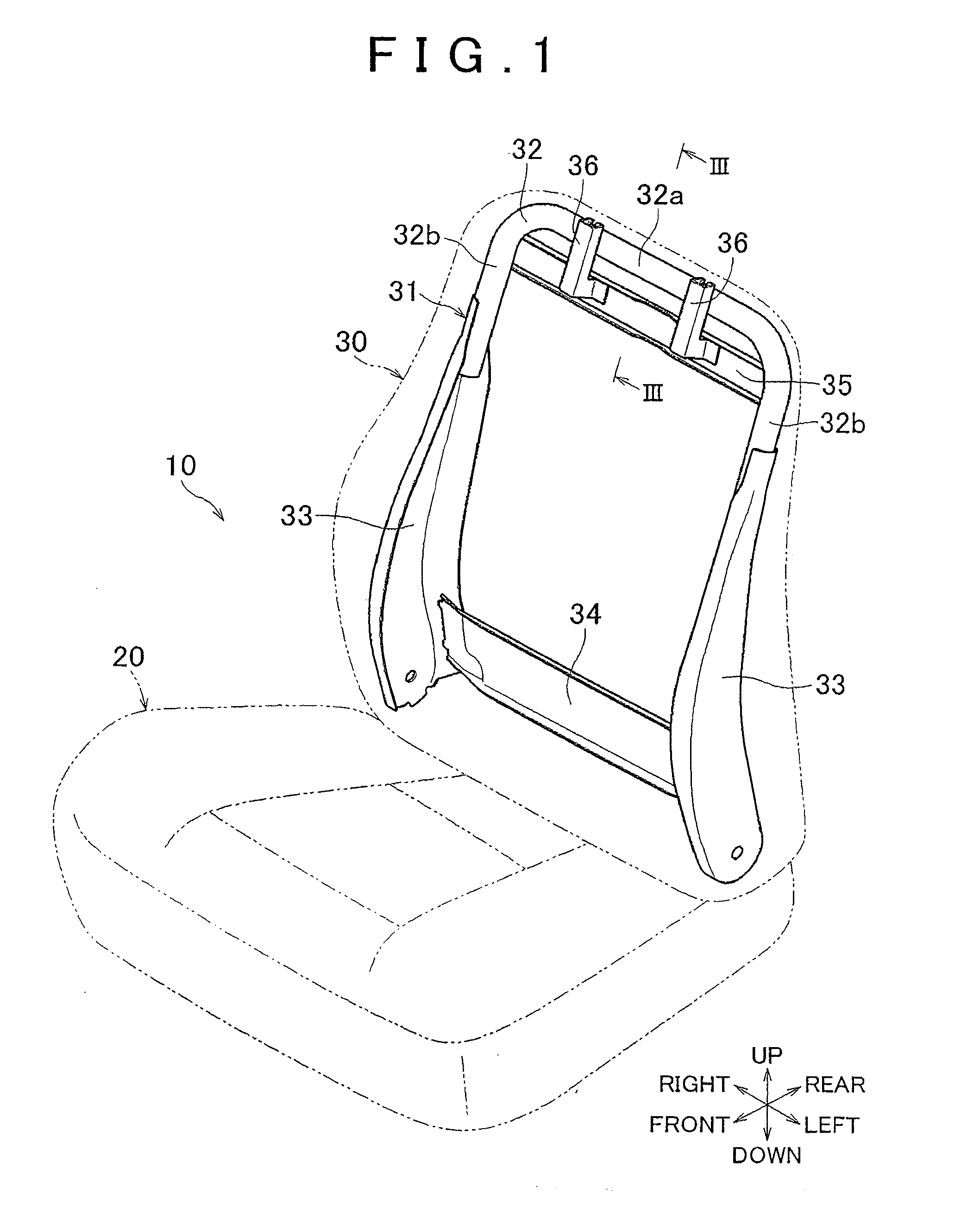
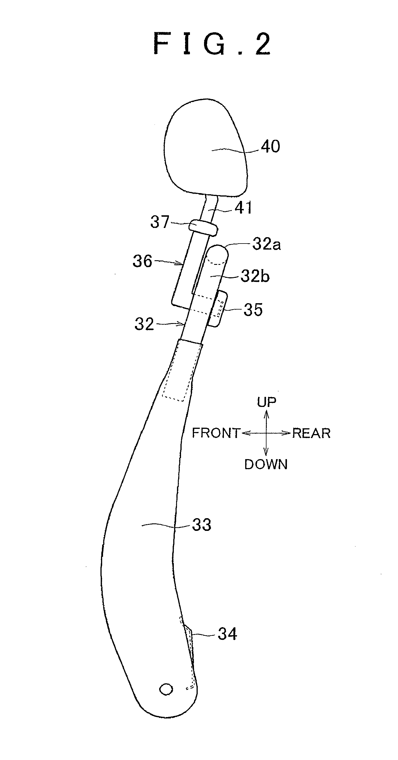
[0027]Hereinafter, example embodiments of the invention will be described with reference to FIGS. 1 to 3. In FIG. 1, the outer shape of a seat 10 provided in a vehicle and used by an occupant is denoted by the alternate long and two short dashes lines. The seat 10 includes a seat cushion 20 on which the occupant sits, a seat back 30 that serves as a backrest for the occupant, and a headrest 40 (see FIG. 2) that supports the head of the occupant. The seat back 30 is connected to a rear end portion of the seat cushion 20. The angle between the seat back 30 and the seat cushion 20 is able to be adjusted by a reclining apparatus, not shown, provided at this connecting portion. The seat back 30 has a metal seat back frame 31 that has a generally rectangular frame shape such as is shown by the solid lines in FIG. 1, as a member that forms the frame of the seat back 30. In addition to the seat back frame 31, the seat back 30 also has a pad member that is a cushion that covers the seat back...


PUM


Abstract

A seat back frame includes an upper frame member that forms an upper side, a reinforcing member that is provided parallel to and below the upper frame member, and a headrest mounting member, that overlaps with both the upper frame member and the reinforcing member. The headrest mounting member is arranged such that, in one location, from among a location where the headrest mounting member overlaps with the upper frame member and a location where the headrest mounting member overlaps with the reinforcing member, the headrest mounting member is fixed to one of the upper frame member and the reinforcing member, and in the other location, the headrest mounting member abuts against the other of the upper frame member and the reinforcing member when the headrest tilts rearward about the one location, such that the tilting of the headrest is inhibited.

Description

INCORPORATION BY REFERENCE[0001]The disclosure of Japanese Patent Application No. 2011-247435 filed on Nov. 11, 2011 including the specification, drawings and abstract is incorporated herein by reference in its entirety.BACKGROUND OF THE INVENTION[0002]1. Field of the Invention[0003]The invention relates to a seat back frame of a vehicle seat, in which a headrest is able to be mounted to an upper portion of the seat back frame.[0004]2. Description of Related Art[0005]In a vehicle seat provided with a headrest for supporting a head of an occupant at an upper portion of a seat back, typically, a metal headrest mounting member is fixed to an upper portion of a seat back frame, and a headrest is attached to this headrest mounting member. More specifically, cylindrical headrest support made of resin is attached to this headrest mounting member, and the headrest is held to the seat back frame by a stay that extends down below the headrest being inserted into this headrest support. A seat ...

Claims


Application Information

Patent Timeline
IPC IPC(8): B60N2/48
CPCB60N2/4885B60N2/68B60N2/888
Inventor MIZOBATA, HIROSHI
Owner TOYOTA BOSHOKU KK
Learn More