Disk drive selecting disturbance signal for feed-forward compensation

a technology of disturbance signal and disk drive, applied in the direction of magnetic recording, data recording, instruments, etc., can solve problems such as disturbance in the servo control system

Active Publication Date: 2013-05-16
WESTERN DIGITAL TECH INC
View PDF6 Cites 108 Cited by
  • Summary
  • Abstract
  • Description
  • Claims
  • Application Information

AI Technical Summary

Problems solved by technology

For example, an external vibration applied to the disk drive or degradation and / or malfunction of the spindle motor that rotates the disks may induce a disturbance in the servo control systems.

Method used


Image

  • Disk drive selecting disturbance signal for feed-forward compensation
  • Disk drive selecting disturbance signal for feed-forward compensation
  • Disk drive selecting disturbance signal for feed-forward compensation

Examples


Embodiment Construction

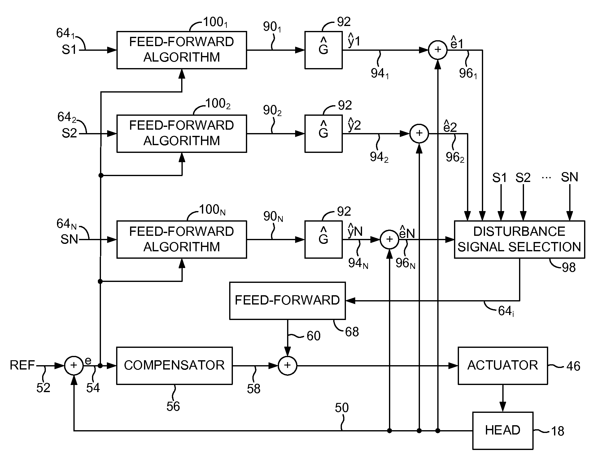
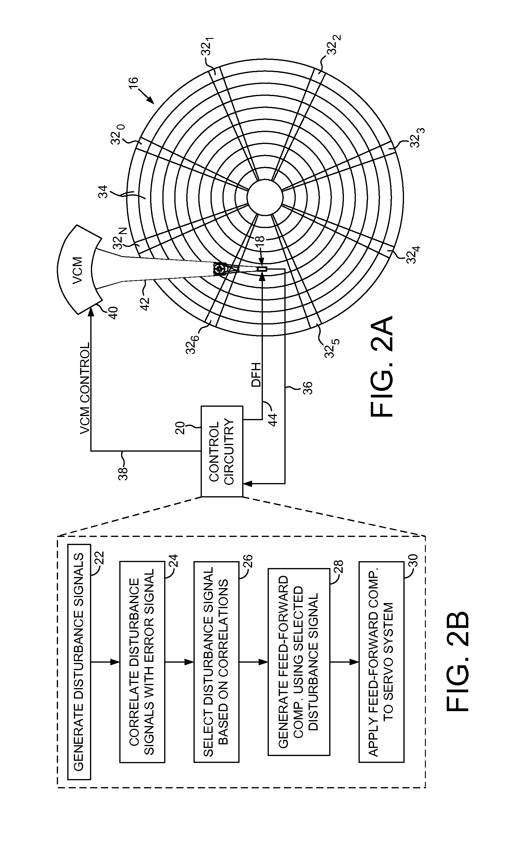
[0017]FIG. 2A shows a disk drive according to an embodiment of the present invention comprising a disk 16, a head 18, and control circuitry 20 comprising a servo control system operable to actuate the head 18 over the disk 16. The control circuitry 20 executes the flow diagram of FIG. 2B, wherein a plurality of disturbance signals is generated in response to a vibration (step 22). A plurality of correlations is generated in response to each disturbance signal and an error signal of the servo control system (step 24). At least one of the disturbance signals is selected in response to the correlations (step 26). A feed-forward compensation value is generated in response to the selected disturbance signal (step 28), and the feed-forward compensation value is applied to the servo control system to compensate for the vibration (step 30).

[0018]In the embodiment of FIG. 2A, the disk 16 comprises embedded servo sectors 320-32N that define a plurality of servo tracks 34. The control circuitr...


PUM

PropertyMeasurementUnit
heightaaaaaaaaaa
phaseaaaaaaaaaa
residual erroraaaaaaaaaa

Abstract

A disk drive is disclosed comprising a disk, a head, and control circuitry comprising a servo control system operable to actuate the head over the disk. A plurality of disturbance signals is generated in response to a vibration. A plurality of correlations is generated in response to each disturbance signal and an error signal of the servo control system. At least one of the disturbance signals is selected in response to the correlations. A feed-forward compensation value is generated in response to the selected disturbance signal, and the feed-forward compensation value is applied to the servo control system to compensate for the vibration.

Description

BACKGROUND[0001]Disk drives comprise a disk and a head connected to a distal end of an actuator arm which is rotated about a pivot by a voice coil motor (VCM) to position the head radially over the disk. The disk comprises a plurality of radially spaced, concentric tracks for recording user data sectors and embedded servo sectors. The embedded servo sectors comprise head positioning information (e.g., a track address) which is read by the head and processed by a VCM servo controller to control the velocity of the actuator arm as it seeks from track to track.[0002]FIG. 1 shows a prior art disk format 2 comprising a number of servo tracks 4 defined by concentric servo sectors 60-6N recorded around the circumference of each servo track, wherein data tracks are defined relative to the servo tracks 4. Each servo sector 6i comprises a preamble 8 for storing a periodic pattern, which allows proper gain adjustment and timing synchronization of the read signal, and a sync mark 10 for storing...

Claims


Application Information

Patent Timeline
Patent Type & Authority Applications(United States)
IPC IPC(8): G11B21/02
CPCG11B5/59694
Inventor ZHOU, JIANGUOXI, WEITU, KUANG-YANGCHAHWAN, ALAIN
Owner WESTERN DIGITAL TECH INC
Why Eureka
Try Eureka