Housing and electronic device

Inactive Publication Date: 2013-05-16
FU TAI HUA IND SHENZHEN +1
View PDF3 Cites 2 Cited by
  • Summary
  • Abstract
  • Description
  • Claims
  • Application Information

AI Technical Summary

Problems solved by technology

During a welding process, a welding portion of the housing can be easily distorted or warped by the wel

Method used


Image

  • Housing and electronic device
  • Housing and electronic device
  • Housing and electronic device

Examples


Embodiment Construction

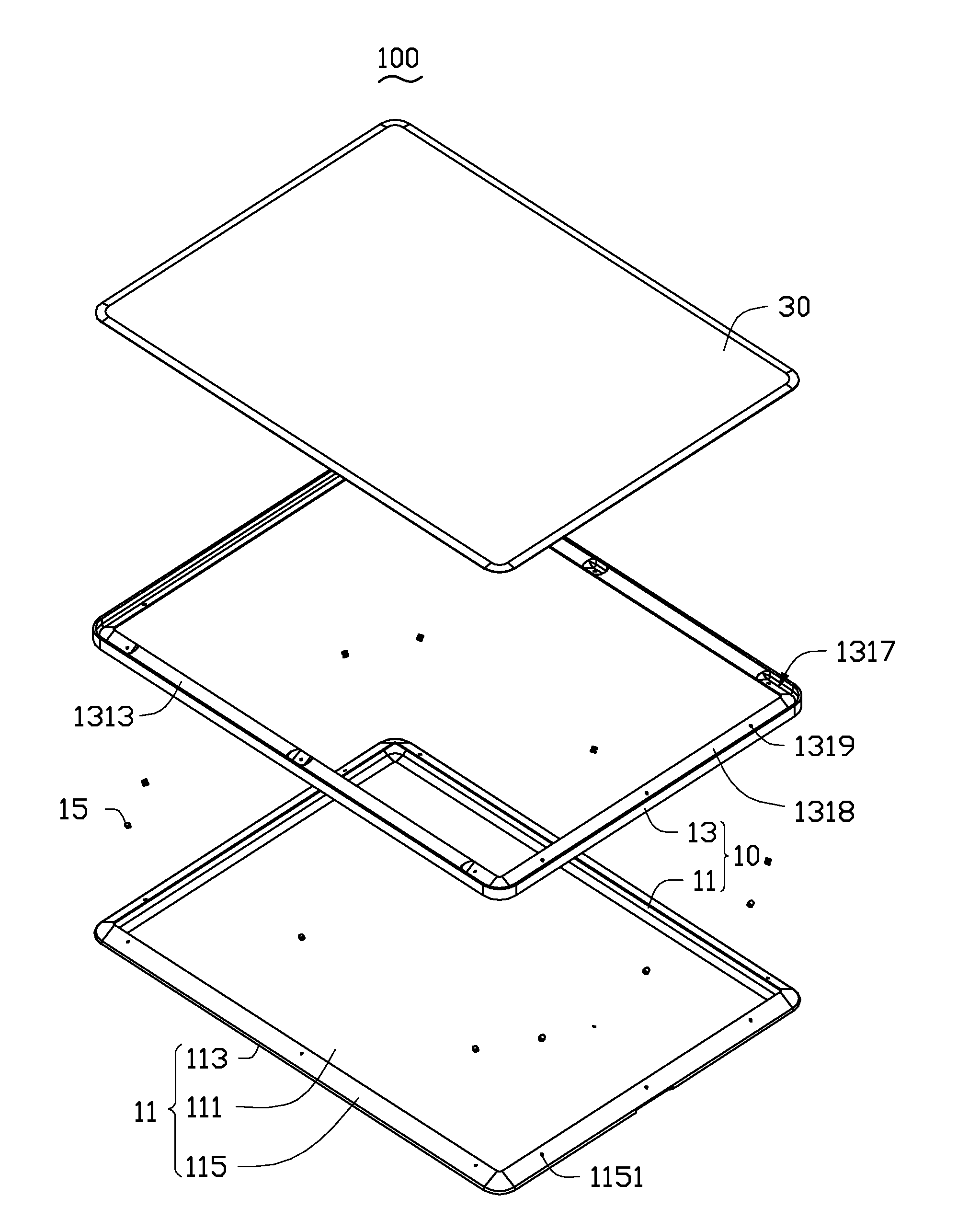
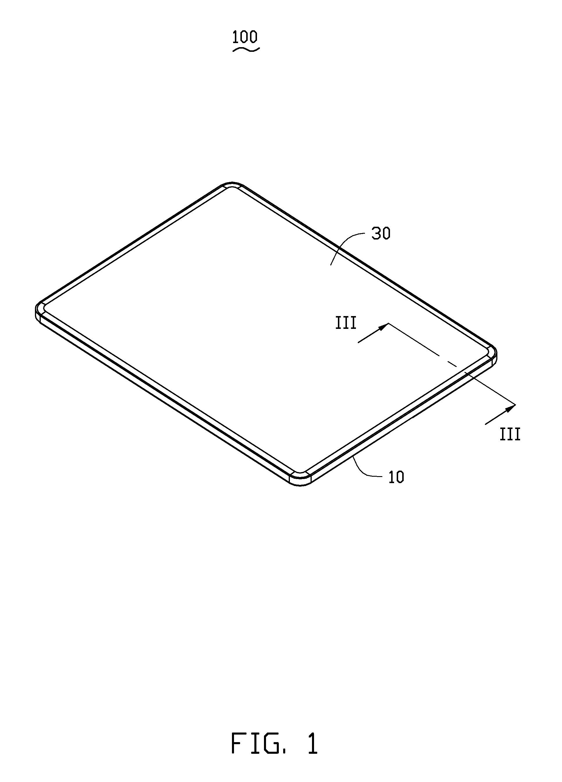
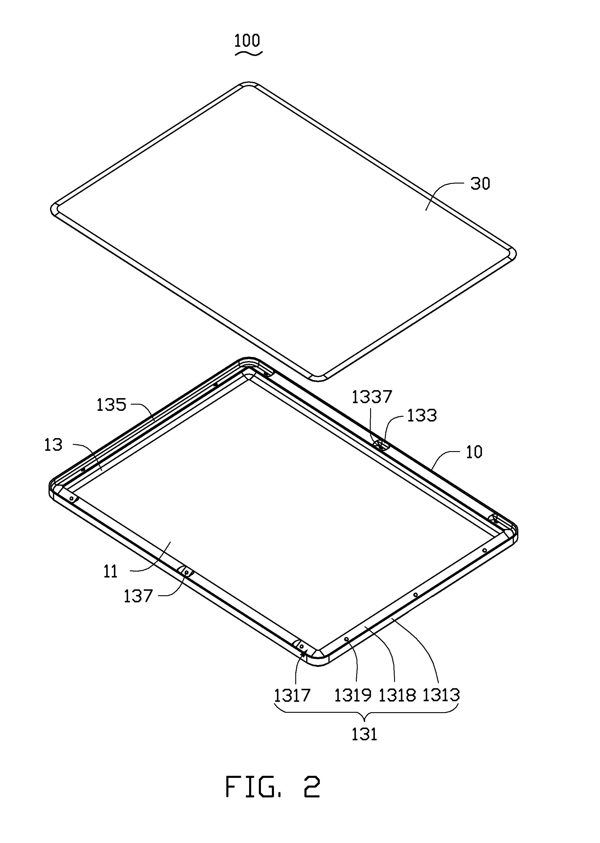
[0012]FIGS. 1 through 3, illustrate an embodiment of an electronic device 100. The electronic device 100 includes a housing 10 and a display screen 30 mounted to the housing 10. The electronic device 100 can be a tablet computer, a mobile phone, an MP3, a PDA, an LCD, or a camera, for example. In the illustrated embodiment, the electronic device 100 is a tablet computer. The electronic device 100 may also include other functional modules to fulfill different functions; however, it is not shown and specifically described for simplification. The housing 10 includes a base housing 11, a reinforcing frame 13, and a plurality of rivets 15 for fixing the base housing 11 and the reinforcing frame 13 together. In the illustrated embodiment, the base housing 11 and the reinforcing frame 13 are both formed by stamping process.

[0013]FIG. 5 shows the base housing 11 of the illustrated embodiment. The base housing 11 includes a base plate 111, a peripheral sidewall 113 slantwise extending outwar...


PUM


Abstract

A housing includes a base housing and a reinforcing frame fixed with the base housing. The base housing includes a base plate, a peripheral sidewall extending outward from a peripheral edge of the base plate, and an inclined supporting peripheral wall extending inward from a distal end of the peripheral side wall toward a central portion of the base plate. The reinforcing frame is securely mounted on the inclined supporting peripheral wall of the base housing. The reinforcing frame includes a mounting portion having an inclined bottom surface resisting against and fixing with the corresponding inclined supporting peripheral wall of the base housing. An electronic device using the housing is also provided.

Description

BACKGROUND[0001]1. Technical Field[0002]The present disclosure generally relates to housing structures, and particularly to a housing and an electronic device using the housing.[0003]2. Description of Related Art[0004]Many electronic devices are equipped with metal housings. In order to decrease a whole weight and a whole thickness of the electronic device, the metal housing is designed to be very thin thus decreasing the strength of the whole structure. In order to increase and ensure the strength of the whole structure of the metal housing, an existing metal housing of an electronic device includes a base housing and a reinforcing frame fixed with the base housing. Generally, the reinforcing frame is welded to the housing. During a welding process, a welding portion of the housing can be easily distorted or warped by the welding process, the whole structure strength and the appearance of the metal housing may easily affected.[0005]Therefore, there is room for improvement within th...

Claims


Application Information

Patent Timeline
IPC IPC(8): H05K5/00
CPCG06F1/1626
Inventor LIANG, YANZHAO, JIAN-ZHOU
Owner FU TAI HUA IND SHENZHEN
Why Eureka
Try Eureka