Power converter based on h-bridges

a power converter and h-bridge technology, applied in the direction of speed controllers, dc-ac conversion without reversal, transportation and packaging, etc., can solve the problems of size, cost and reliability constraints of known regenerative power converter topologies comprenant h-bridges

Inactive Publication Date: 2013-05-16
GENERAL ELECTRIC CO
View PDF9 Cites 39 Cited by
  • Summary
  • Abstract
  • Description
  • Claims
  • Application Information

AI Technical Summary

Problems solved by technology

Known regenerative power converter topologies comprising H-bridges continue to struggle with size, cost and reliability constraints due to the high number of active switches required to provide a workable topology.

Method used


Image

  • Power converter based on h-bridges
  • Power converter based on h-bridges
  • Power converter based on h-bridges

Examples


Embodiment Construction

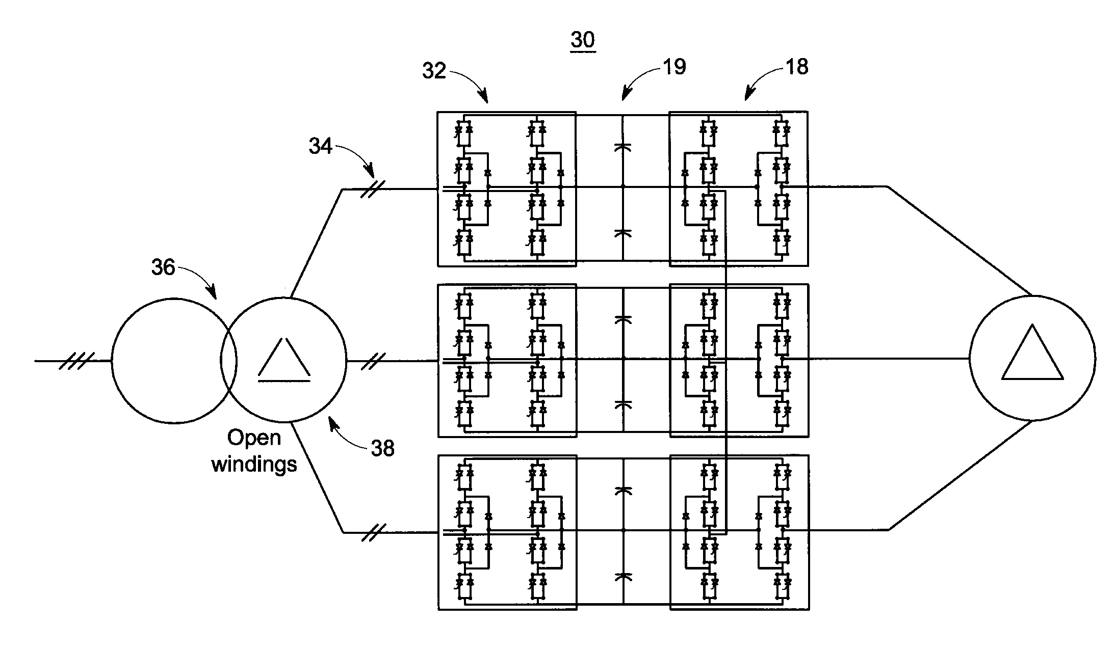
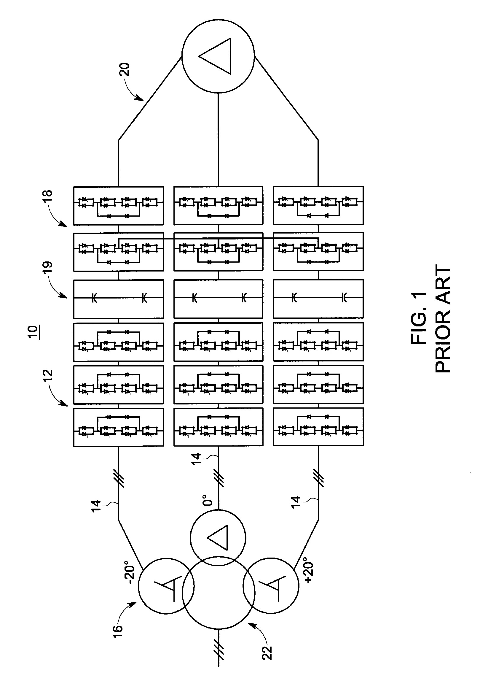
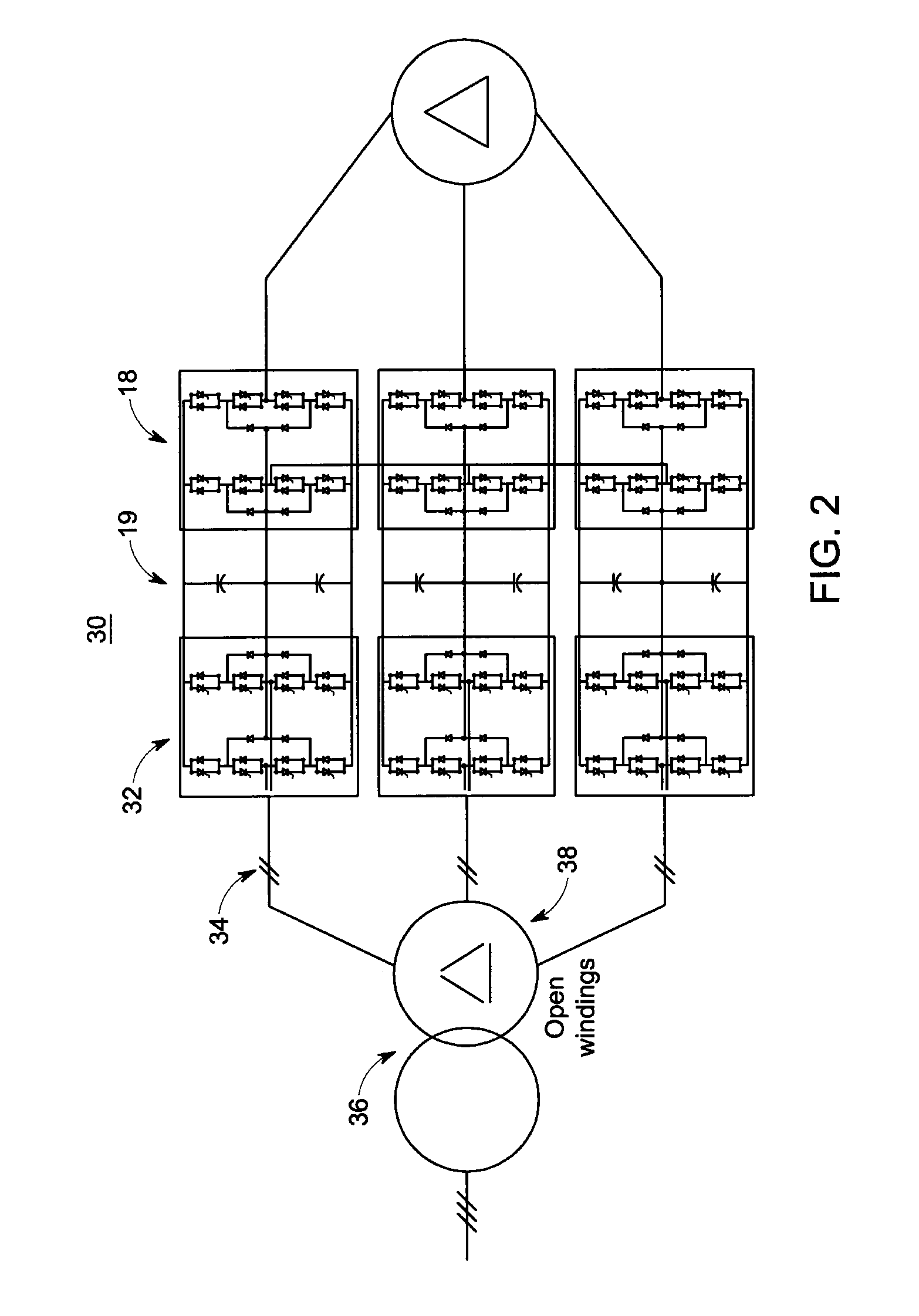
[0033]FIG. 1 is a simplified diagram illustrating a regenerative converter topology 10 that is known in the art. It can be seen that the converter 10 employs a high parts count active front end (AFE) converter 12 per phase since it requires the use of 9 phase connections 14 and converter phase-legs in the converter 12 to connect with one or more conventional three-phase transformers 16. The drawing figures throughout have been simplified with small hashes crossing single line connections for ease of understanding. These small hashes are used to indicate the number of real connection wires which are represented by the single line diagrams.

[0034]The converter 10 can be seen to also employ a plurality of H-bridge inverters 18 that are each coupled to a corresponding AFE converter 12 via a corresponding dc-link 19. One output of each H-bridge inverter 18 of the three phases is generally connected to a corresponding output of each other H-bridge inverter 18. Each other H-bridge inverter ...


PUM


Abstract

A power converter includes an active front end (AFE) that is coupled by a dc link stage to a plurality of H-bridge inverters. One or more multi-phase electro-magnetic energy conversion devices, such as transformers or electric machines, with open windings that are connected to only the AFE or only the H-bridge inverters or to both the AFE and H-bridge inverters, provide a regenerative or partial regenerative power converter.

Description

BACKGROUND[0001]The subject matter of this disclosure relates generally to power converters, and more particularly to power converter topologies based on H-bridges that are coupled to one or more multi-phase electromagnetic energy conversion devices (EMECDs), including without limitation, multi-phase transformers with open windings and / or electric machines with open windings, to provide a regenerative or partial regenerative power converter.[0002]Power converter cell topologies associated with variable frequency drive (VFD) applications continue to receive attention. New power converter cell topologies are continually being introduced. Some known power converter cell topologies have employed H-bridge converters and / or H-bridge inverters.[0003]Some of the foregoing power cells, when connected to a load, such as a motor, can provide power from an input source to a motor when operating in the motoring mode. Such a power cell may sometimes be referred to as a unidirectional or two-quadr...

Claims


Application Information

Patent Timeline
Patent Type & Authority Applications(United States)
IPC IPC(8): H02M5/458
CPCB60L15/007H02M5/4585H02M1/12H02M7/49H02M7/487H02M1/0095Y02T10/64
Inventor SCHROEDER, STEFANWIJEKOON, PINIWAN THIWANKA BANDARA
Owner GENERAL ELECTRIC CO
Why Eureka
Try Eureka