Crushing machines

a technology of crushing machine and screen, which is applied in the field of crushing machine, can solve the problems of not being pleasant for operators and extensive damage, and achieve the effect of facilitating screen chang

Active Publication Date: 2013-05-23
TEREX GB
View PDF2 Cites 4 Cited by
  • Summary
  • Abstract
  • Description
  • Claims
  • Application Information

AI Technical Summary

Benefits of technology

[0017]The screen conveyor is conveniently mounted on the frame by a further pair of piston and cylinder assemblies. These enable the angle of the screen co

Problems solved by technology

However, it is important to ensure that no metal is fed into the crusher, since this can cause

Method used


Image

  • Crushing machines
  • Crushing machines
  • Crushing machines

Examples


Embodiment Construction

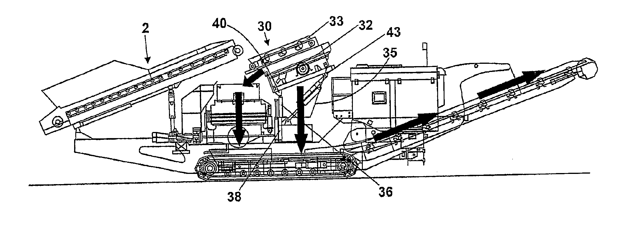
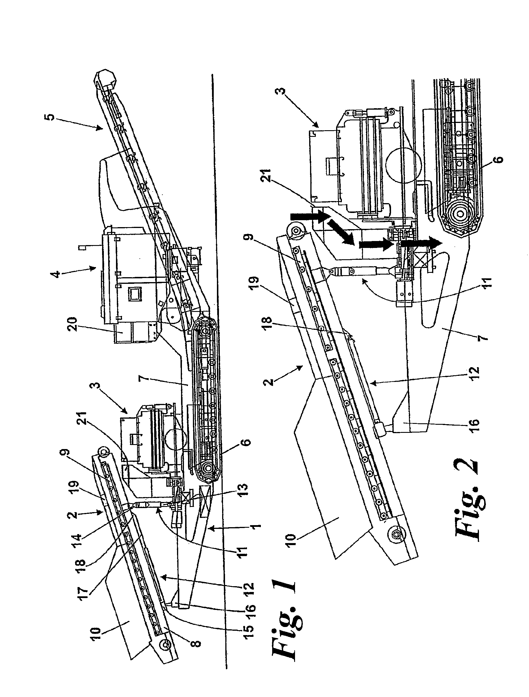
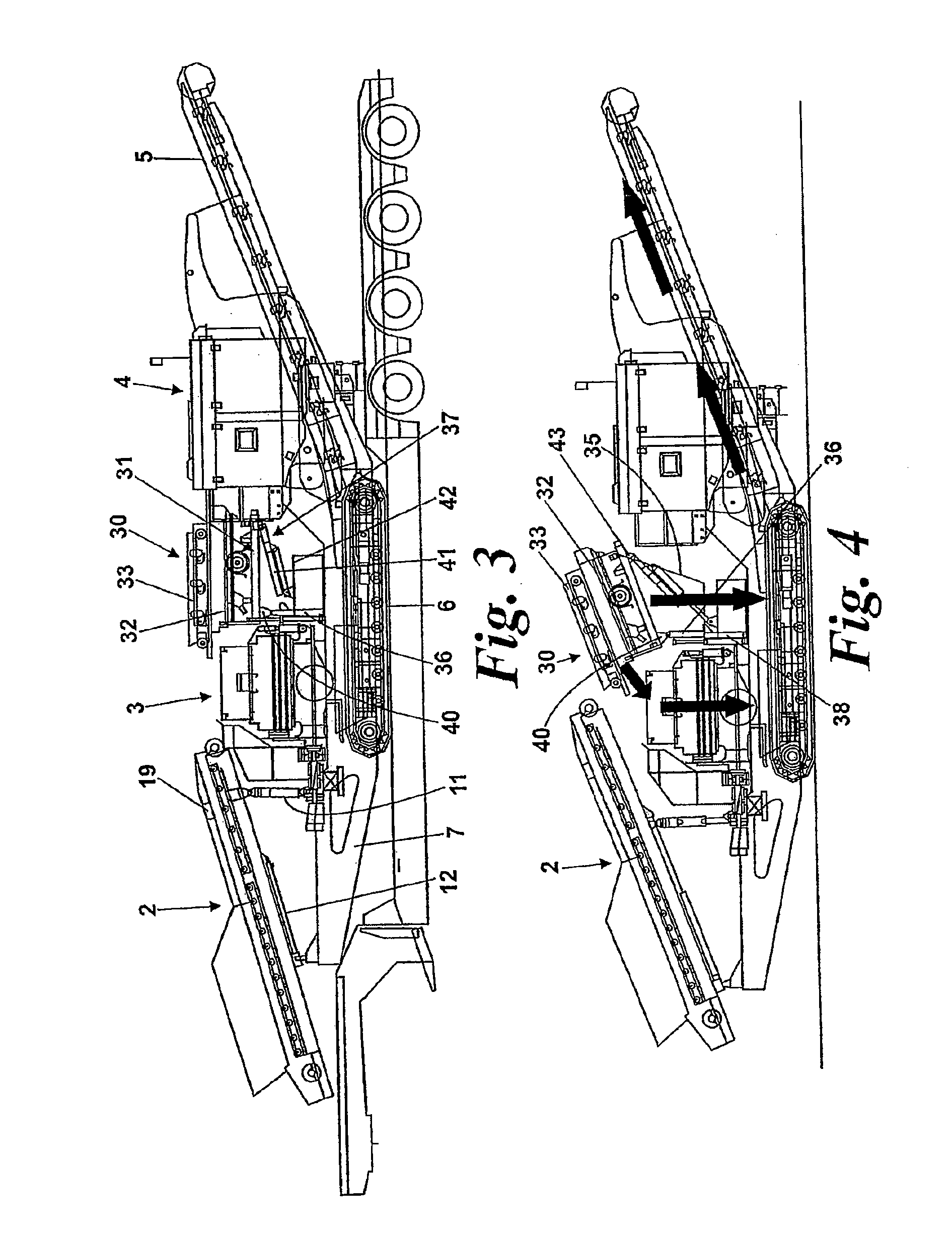
[0025]The machine of FIG. 1 is a mobile crushing machine for crushing stone, aggregate and the like. The machine comprises a base 1, on which are mounted a feed conveyor 2, crushing means 3, a power unit 4 including a control unit, and a main conveyor 5.

[0026]The base 1 has tracks 6 and an elongate platform 7 on which the other parts are mounted. with the feed conveyor 2 at the rear end, and the main conveyor 5 at the front end.

[0027]The feed conveyor 2 is of a known design having a frame 8 for a powered belt 9 and a feed chute 10 at the rear end of the belt 9 to receive material to be crushed.

[0028]The frame 8 is mounted on the platform 7 by two pairs of hydraulic piston and cylinder assemblies 11, 12. The assemblies 11 act vertically to raise and lower the forward end of the frame 8 with the cylinders 13 being attached to the platform 7, and the pistons 14 pivotally mounted to the frame 8. The assemblies 12 act to move the frame 8 in the longitudinal direction between the normal o...


PUM


Abstract

A crushing machine including a crushing means, a feed conveyor for feeding material to the crushing means, a detector for detecting metal in the material on the feed conveyor, and a bypass chute for the crushing means, the feed conveyor being movable between a normal operating position in which the material is fed to the crushing means and a bypass position in which the material is fed to the bypass chute, the arrangement being such that on detection of metal in the material, the feed conveyor is stopped and moved from the normal operating position to the bypass position so that the material with the metal is discharged into the bypass chute.

Description

CROSS-REFERENCE TO RELATED APPLICATIONS[0001]This application is a divisional application and claims priority to allowed U.S. patent application Ser. No. 12 / 596,943 filed on Oct. 21, 2009 titled “Crushing Machines”, which is a U.S. National Stage filing under 35 U.S.C. §371 of International Application No. PCT / GB08 / 01396 filed on Apr. 21, 2008, which claims priority to United Kingdom Patent Application No. 0707761.3 filed on Apr. 21, 2007, the disclosures of each of which are incorporated herein.BACKGROUND OF THE INVENTION[0002]This invention relates to crushing machines for crushing aggregate and the like; and in particular to mobile crushing machines such as are used in quarries or for recycling demolition waste.[0003]One type of crushing machine uses a crusher. A cone crusher has a pair of frusta-conical members arranged with their apexes upwards, and with an annular gap between them that decreases in width from top to bottom. The inner cone is rotatable relative to the outer con...

Claims


Application Information

Patent Timeline
IPC IPC(8): B02C2/00B02C23/08
CPCB02C21/026B02C23/02B02C2/007B02C23/08B02C23/04Y10T29/49826
Inventor ROBINSON, KARLNEVIN, JONATHANDEVLIN, ANTHONY
Owner TEREX GB
Why Eureka
Try Eureka