Method and control device for controlling power flow within a DC power transmission network

Active Publication Date: 2013-05-23
HITACHI ENERGY SWITZERLAND AG
View PDF0 Cites 12 Cited by
  • Summary
  • Abstract
  • Description
  • Claims
  • Application Information

AI Technical Summary

Benefits of technology

[0025]In another embodiment, the method comprises the further step of filtering the common feedback signal by the low-pass filter before using it in regulating voltage and/or power of the converter station. The cut-off frequency of the filter may advantageously be chosen low, thereby capturing the steady state behavior of the common feedback signal. The dynamic performance of t

Problems solved by technology

If extending the above concept, i.e. of having one station in DC voltage control and the other stations in power control, to the multi-terminal DC grid one would encounter several difficulties.
If a converter other than the DC voltage controlling station is disconnected due to a fault, the DC voltage controlling station would have to pick up the load of the failed converter station.
Further, the AC system connected to the DC voltage controlling station would be exposed to large power swings if converter stations are lost.
If the DC voltage controlling statio

Method used


Image

  • Method and control device for controlling power flow within a DC power transmission network
  • Method and control device for controlling power flow within a DC power transmission network
  • Method and control device for controlling power flow within a DC power transmission network

Examples


Embodiment Construction

[0041]Same reference numerals are used throughout the figures for denoting same or corresponding parts.

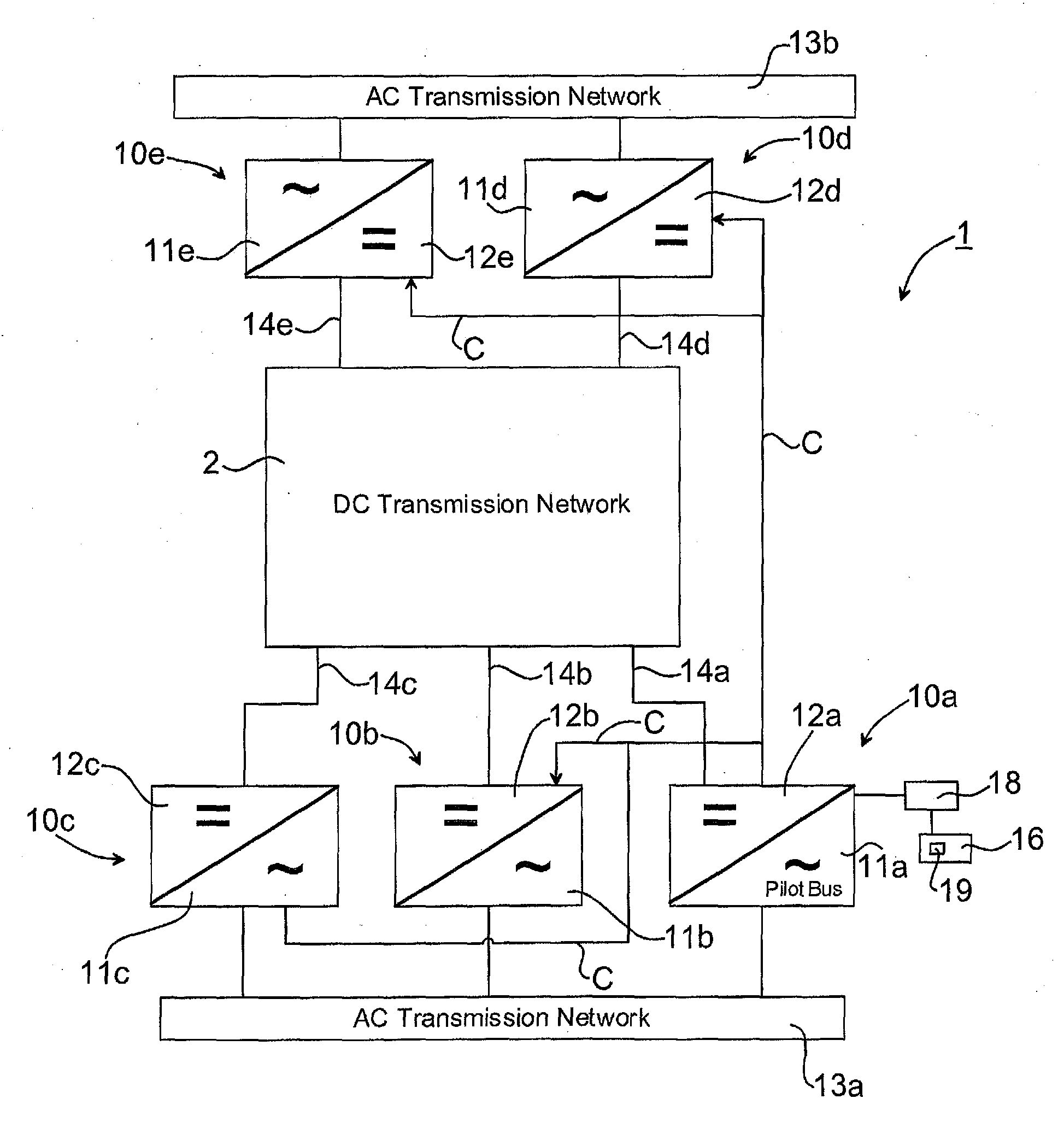
[0042]FIG. 2a illustrates a multi-terminal DC power transmission system 1, in the following denoted DC grid 1 for simplicity, in accordance with the invention. The DC grid 1 is preferably a high voltage (HV) DC grid and comprises any number of converter stations, although 5 converter stations are illustrated in FIG. 2a. The converter stations 10a, 10b, 10c, 10d, 10e in turn comprise inverters converting DC to AC and / or rectifiers converting AC to DC. Other components and means conventionally used within a power network for enabling DC power transmission, but not forming part of the invention, may also be included but are omitted from the description and figures in order of simplicity.

[0043]The converter stations 10a, 10b, 10c, 10d, 10e comprises an AC side 11a, 11b, 11c, 11d, 11e connectable to an AC network 13a, 13b. It is noted that there could be another number of AC networks. T...


PUM


Abstract

A method for controlling power flow within a DC power flow within a DC power transmission network includes two or more interconnected converter stations. The method includes the steps of: establishing a common feedback signal (Ud,common, Ũd,common) to the converter stations, the common feedback signal (Ud,common, Ũd,common) being based on an overall voltage level in the DC transmission, power network; providing, in the converter stations, a control signal (S1, S2, S3, S4) based on the common feedback signal (Ud,common) and a drooped error signal (Pe, droop, Ue, droop); and controlling the power flow within the DC power transmission network towards set operating points (Udref, PCCref) by using the control signal (S1, S2, S3, S4). A control device and computer program product is also described.

Description

FIELD OF THE INVENTION[0001]The invention relates generally to the field of power transmission systems, and in particular to power flow control in multi-terminal DC power transmission systems.BACKGROUND OF THE INVENTION[0002]Control of High Voltage Direct Current (HVDC) power transmission systems, denoted DC grids in the following, is a challenging task and HVDC transmissions have up to date essentially equaled point-to-point two station transmissions. However, the introduction of voltage source converter (VSC) technology has provided the possibility of controlling larger DC grids, i.e. controlling multi-terminal DC grids.[0003]FIG. 1 illustrates a simplified single line diagram of a VSC converter. The VSC converter is on its AC side connected to a point of common coupling (PCC) in an ac network and on its dc side connected to a dc transmission.[0004]Conventionally, the VSC converter station is controlled by controlling AC voltage UPCC at the PCC or the amount of reactive power inje...

Claims


Application Information

Patent Timeline
IPC IPC(8): G05F1/66
CPCH02J1/102H02J1/12Y02E60/60H02J3/36G05F1/66H02J1/14
Inventor BERGGREN, BERTILMAJUMDER, RAJATSAO, CHARLESLINDEN, KERSTIN
Owner HITACHI ENERGY SWITZERLAND AG
Why Eureka
Try Eureka