Method of polishing bladed disks for a turbomachine and polishing device

a technology of bladed disks and turbomachines, which is applied in the direction of machines/engines, manufacturing tools, liquid fuel engines, etc., can solve the problems of high labor costs, inability to obtain the roughness value directly, and long time-consuming polishing, etc., and achieves simple and robust effects

Active Publication Date: 2014-02-25
SN DETUDE & DE CONSTR DE MOTEURS DAVIATION S N E C M A
View PDF14 Cites 6 Cited by
  • Summary
  • Abstract
  • Description
  • Claims
  • Application Information

AI Technical Summary

Benefits of technology

[0019]Thus the movement of the polishing agent relative to the blading is substantially that of the flow of the air between the blades, which improves the performance of the method.
[0034]Particularly advantageously, the face of the plate intended to be in contact with the disk comprises an annular slot receiving a sealing device intended to come into contact with the disk and prevent the polishing agent from penetrating between the disk and the plate.

Problems solved by technology

However, this roughness value cannot be obtained directly by machining, casting or another technique for making the impeller.
However, this polishing takes a very long time, and is therefore costly in terms of labor.
Machines, like those described in U.S. Pat. No. 2,547,056, can be used, but they are very complex structures and do not make it possible to polish parts with complex shapes.
With this technique, there is a risk of not achieving the desired surface parameter Ra due to stagnation of the abrasive particles in the zones in question.

Method used


Image

  • Method of polishing bladed disks for a turbomachine and polishing device
  • Method of polishing bladed disks for a turbomachine and polishing device
  • Method of polishing bladed disks for a turbomachine and polishing device

Examples


Embodiment Construction

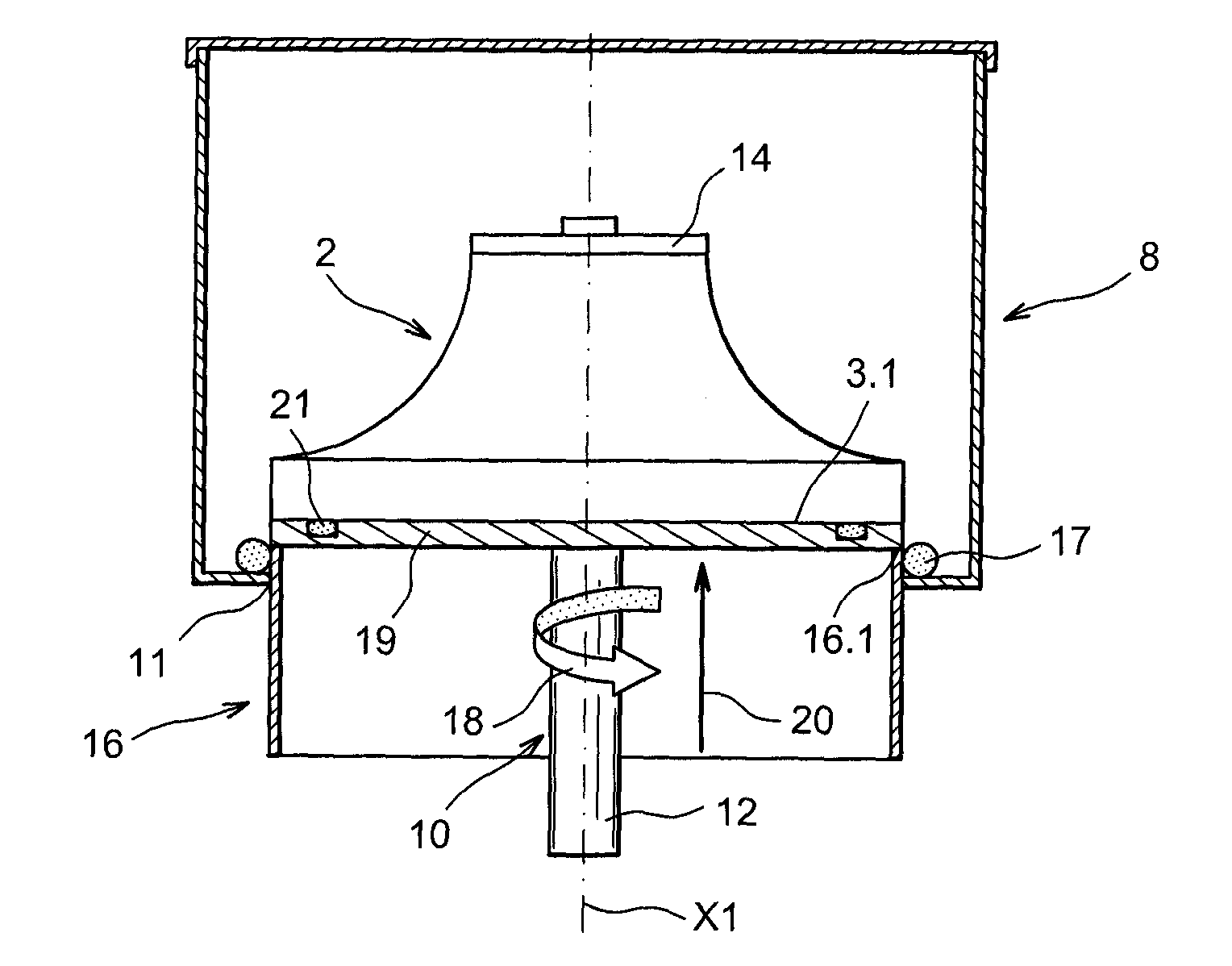
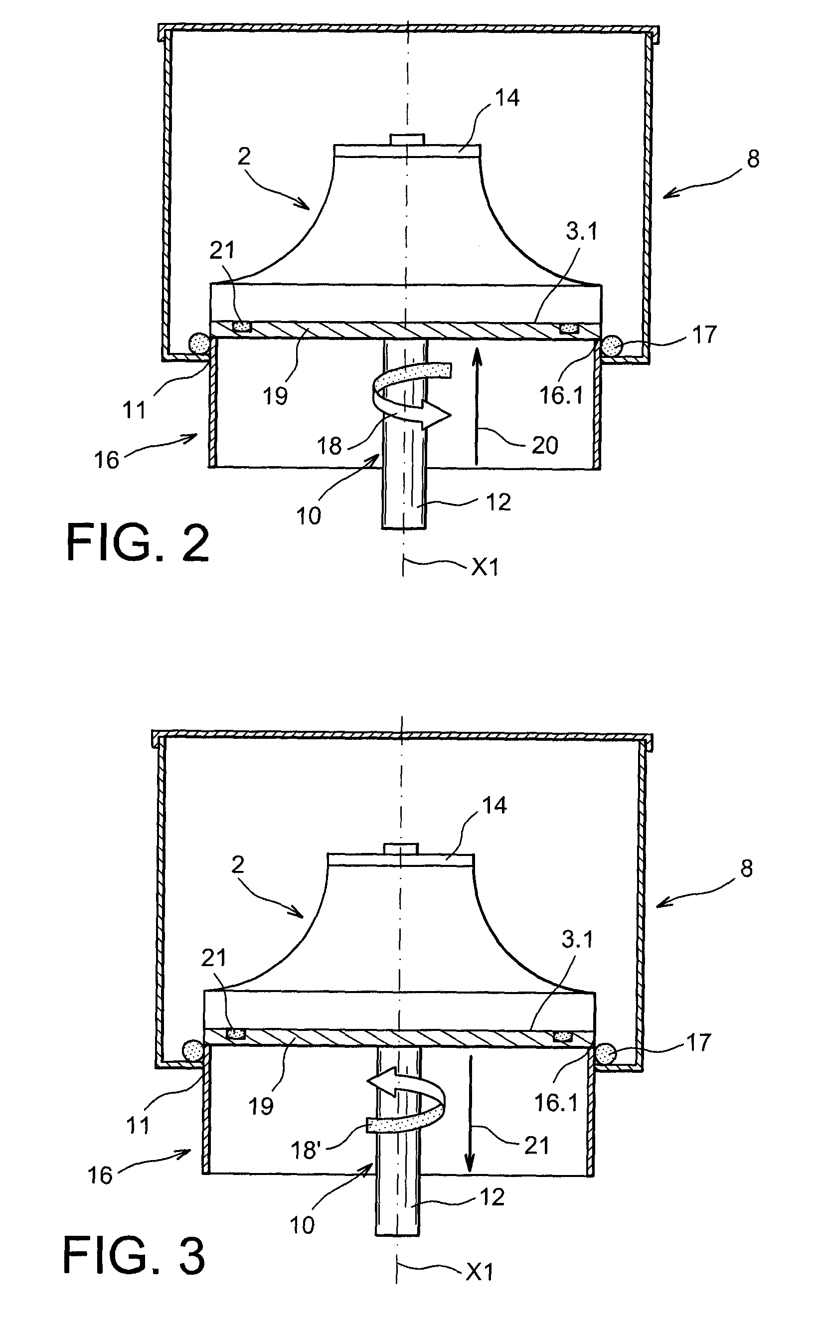
[0044]In the continuation of the description, we will apply the polishing method to a centrifugal compressor impeller of a turbomachine compressor, but the present invention is applicable to any bladed part, such as a single-piece bladed disk used in a turbine.

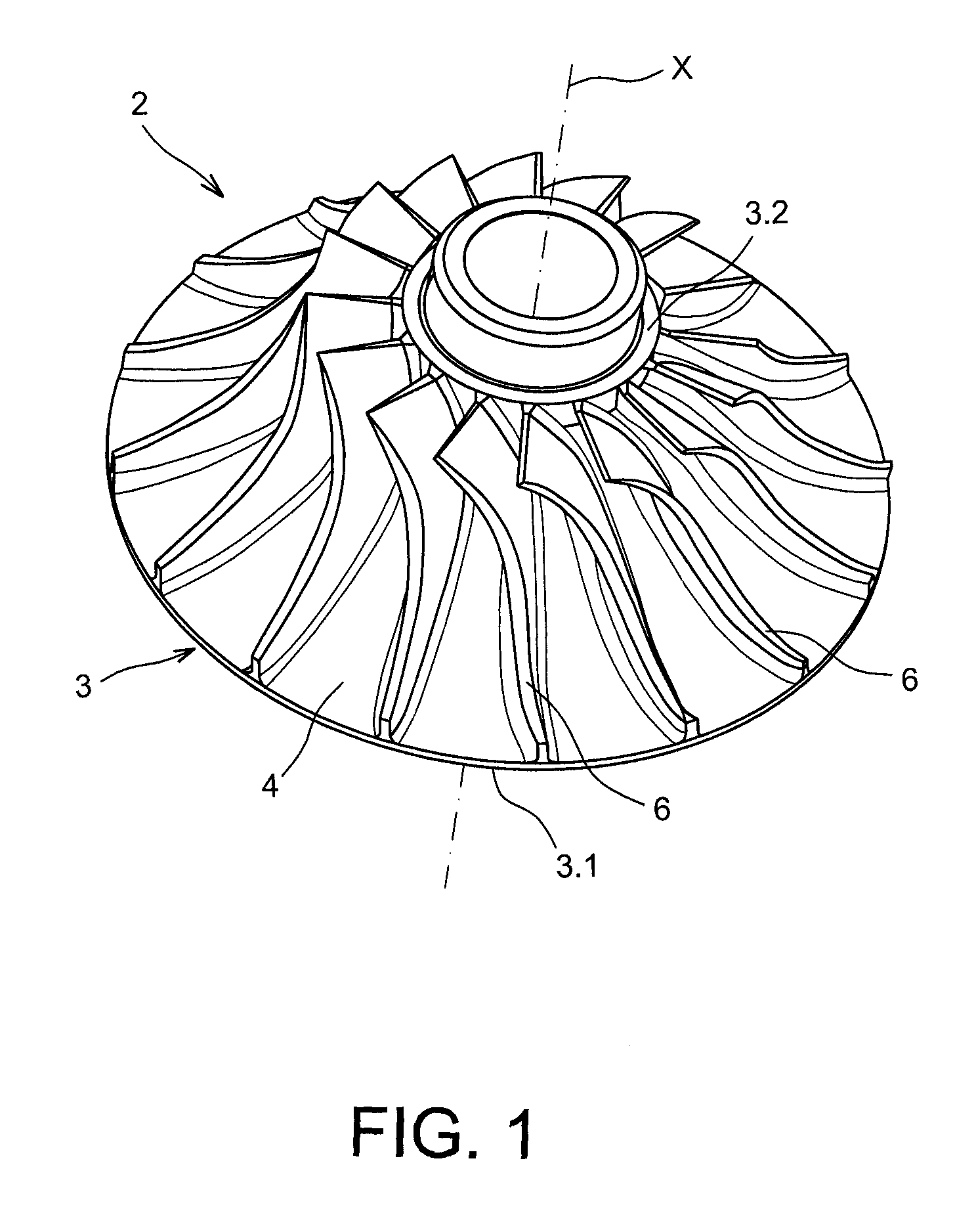
[0045]FIG. 1 shows an example of a centrifugal impeller 2 of a compressor to which the invention is applied.

[0046]A centrifugal compressor impeller is a part rotationally mobile around the longitudinal axis of the turbomachine and is driven by the turbine.

[0047]The impeller 2 comprises a substantially annular flange 3 with axis X. The flange 3 comprises, at a first longitudinal end, a large base 3.1 with a larger diameter and, at a second longitudinal end, a small base 3.2 with a smaller diameter, the larger diameter and the smaller diameter being connected by a concave annular surface 4 called a channel.

[0048]The impeller 2 also comprises blades 6 protruding from the concave annular surface 4. The blades 6 are regularly distr...


PUM

PropertyMeasurementUnit
Raaaaaaaaaaa
displacement speedaaaaaaaaaa

Abstract

A device for polishing centrifugal impellers for a turbomachine including a vat configured to be filled with a polishing agent, and an impeller support configured to make the impeller rotate around its axis and move it along its axis such that all of points of the impeller have a helical movement whereof the pitch is close to that of the helix from which the general shape of the airflow channels of the impeller comes, delimited by the blades of the impeller.

Description

TECHNICAL FIELD AND BACKGROUND OF THE INVENTION[0001]The present invention relates primarily to a method for polishing bladed disks and comprising an airflow channel for a turbomachine, more particularly a method for polishing centrifugal impellers for a turbomachine compressor and single-piece bladed disks, and a polishing device for implementing such a method.[0002]Turbomachines traditionally comprise a compressor, a compression chamber and a turbine.[0003]The compressor is intended to increase the pressure of the atmospheric air, the combustion chamber mixes the air that is compressed by the compressor with fuel and burns the mixture, and the turbine, placed in the discharged flow, is driven by that flow of very hot air. It serves to drive the compressor via the axis of the turbomachine.[0004]The compressor comprises rotors, said rotors comprising bladed disks, some of which are called centrifugal impellers, and stators. A centrifugal compressor impeller, hereinafter called impel...

Claims


Application Information

Patent Timeline
Patent Type & Authority Patents(United States)
IPC IPC(8): B24B31/00
CPCF04D29/02F04D29/023F01D5/005B24B31/003F04D29/321F04D29/284F05D2230/90F05D2250/621F05D2300/516
Inventor BAUDIMONT, CYRILLECHABOT, JEAN-FRANCOIS LAURENT
Owner SN DETUDE & DE CONSTR DE MOTEURS DAVIATION S N E C M A
Why Eureka
Try Eureka