Physical Simulation Tools For Two-Dimensional (2D) Drawing Environments

a simulation tool and drawing environment technology, applied in the field of physical simulation tools for two-dimensional (2d) drawing environments, can solve the problems of complex 3d modeling, specialized software and complex methods that are not easily accessible to designers, artists, or others, and not provide easily accessible and intuitive tools for applying simulations on 2d designs. achieve the effect of realistic visual effects

Active Publication Date: 2013-05-23
ADOBE INC
View PDF3 Cites 22 Cited by
  • Summary
  • Abstract
  • Description
  • Claims
  • Application Information

AI Technical Summary

Benefits of technology

[0006]In at least some embodiments, any one of various types of predefined physical materials or substances may be specified for a 2D object to which a 2D physical simulation tool may be applied. Each predefined material may be specified by various physical properties of the materials, such as elasticity, strength, viscosity, hardness, ignition point, and so on. However, rather than setting values for these various physical parameters manually, as in conventional physical simulations, a simple material property may be assigned to a 2D object, such as “ceramic”, “metal”, “rubber”, “wood”, etc. These simple material properties provide intuitive labels for collections of the physical properties and set expectations for what happens when the physical simulation is run based on the known behaviors of the actual physical materials.
[0007]In at least some embodiments, at least some of the 2D physical simulation tools may each have one or more tool-specific parameters that may affect the physical simulations initiated by applications of the tools to objects. In at least some embodiments, one or more of the tool-specific parameters may be adjustable to vary the physical effect caused by the respective tool. In at least some embodiments, one or more global simulation parameters may affect the operation of the physical simulators associated with the 2D physical simulation tools. In at least some embodiments, one or more of the global simulation parameters may be adjustable. The global simulation parameters are independent of the various material properties of the objects being acted upon.
[0008]Embodiments may enable the physical simulations to be executed in real-time or near-real-time as the tools are applied, thus providing immediate feedback and realistic visual effects. To achieve this, the physical simulations may be performed on 2D mesh representations, or tessellations, of the 2D objects. In addition, in at least some embodiments, computing technology, including but not limited to GPU (Graphic Processing Units) and multi-core CPUs, may be leveraged to enable the physical simulations to be executed in real-time or near-real-time. In at least some embodiments, portable parallelism libraries, such as OpenCL, and platform specific math libraries may be leveraged to provide the computational resources necessary for near-real-time or real-time performance.
[0009]In at least some embodiments of a method for applying 2D physical simulation tools to 2D objects to achieve various simulated physical effects associated with the tools, a 2D physical simulation tool may be selected. For example, a physical simulation tool may be selected from a tool palette provided by a user interface. A 2D graphic object may be selected, for example from a working digital image displayed on the user interface. In at least some embodiments, a material for the selected object may be specified, for example via a materials palette provided by the user interface. A mesh representation of the object may be generated, if necessary. The mesh breaks the arbitrary shape into small, discrete units, which may be but are not necessarily triangles, required for performing the physical simulation. To initiate a physical simulation, the user may apply the selected tool to the selected object. For example, via the user interface, the user may place the tool near a desired area of the selected object, or may apply a simple gesture, depending on the selected tool. The respective physical simulation may be applied to the object in response to the application of the tool, and the effects of the physical simulation may be displayed. Note that the physical simulation may be iteratively applied, and the effects may be, but are not necessarily, displayed at each iteration. An iteration may be defined as a single step of a physical simulation applied to an object over a particular time interval, where the time interval corresponds to the animation of the effect (e.g., 1 / 30th of second). In at least some embodiments, for at least some tools, the physical simulation may be performed on a mesh representation of the object, rather than on the object itself.
[0010]While the 2D physical simulation tools are generally described herein in relation to simulating physical effects in static 2D images, the 2D physical simulation tools may also be extended to 2D animation. For example, in at least some embodiments, the results of each iteration of a physical simulation may be preserved, and the resulting series of results may be stored as or used to generate an animation sequence for the physical effect caused by the selected tool being applied to the object.

Problems solved by technology
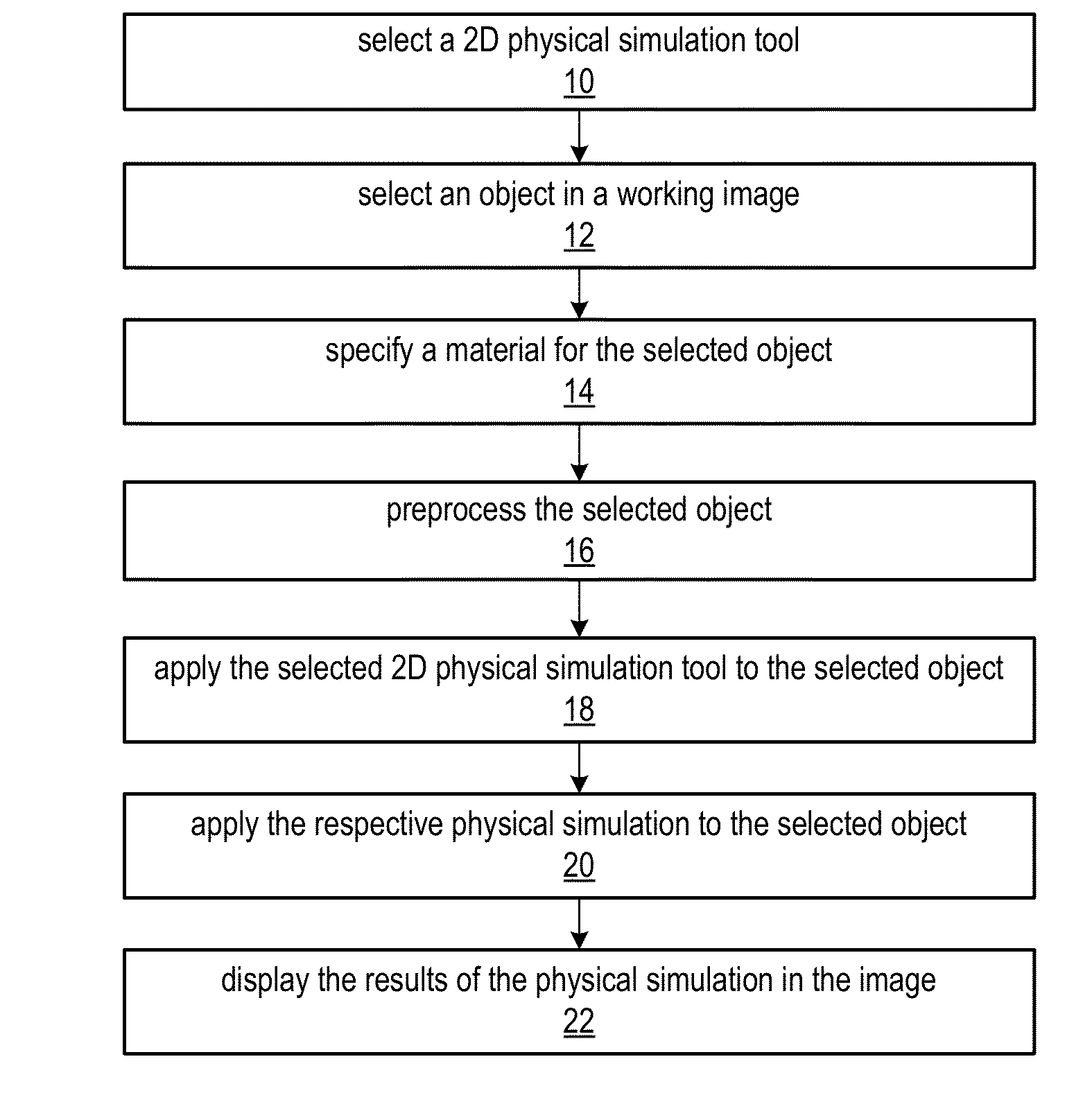
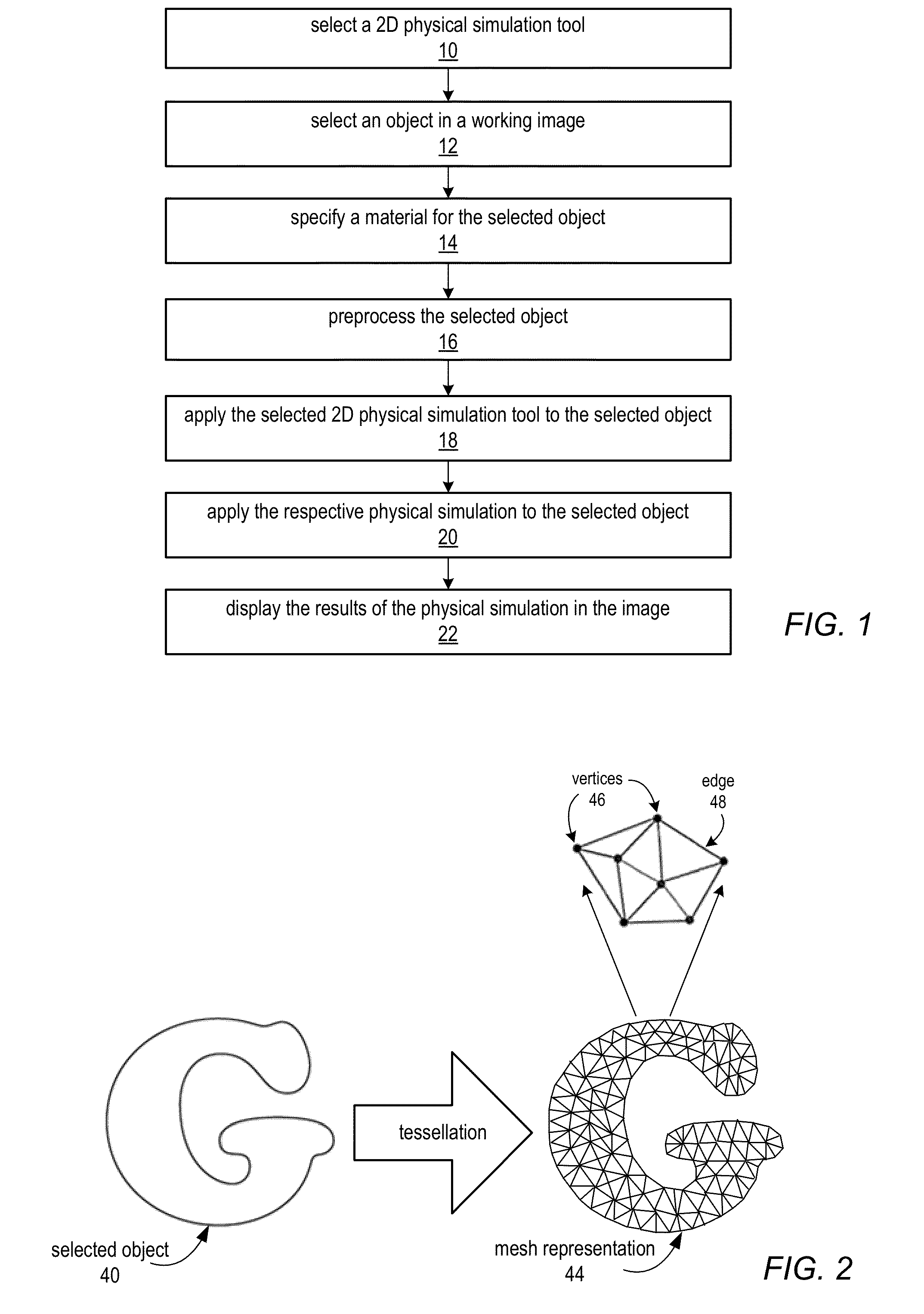
Conventional methods for generating these effects, however, typically require very specialized software and complex 3D modeling that is not easily accessible to designers, artists, or others using conventional two-dimensional (2D) drawing tools.
However, these conventional physical simulation techniques typically assume a complex 3D environment for setting up the simulation, and do not provide easily accessible and intuitive tools for applying the simulations on 2D designs.
However, these games and applications concentrate primarily on simple mechanics demonstration, and do not provide simulations that actually modify objects as editing tools.
However, conventional commercial simulation engines typically assume a complex 3D modeling setup, and typically do not provide simple and intuitive tools.

Method used


Image

  • Physical Simulation Tools For Two-Dimensional (2D) Drawing Environments
  • Physical Simulation Tools For Two-Dimensional (2D) Drawing Environments
  • Physical Simulation Tools For Two-Dimensional (2D) Drawing Environments

Examples


Embodiment Construction

[0027]In the following detailed description, numerous specific details are set forth to provide a thorough understanding of claimed subject matter. However, it will be understood by those skilled in the art that claimed subject matter may be practiced without these specific details. In other instances, methods, apparatuses or systems that would be known by one of ordinary skill have not been described in detail so as not to obscure claimed subject matter.

[0028]Some portions of the detailed description which follow are presented in terms of algorithms or symbolic representations of operations on binary digital signals stored within a memory of a specific apparatus or special purpose computing device or platform. In the context of this particular specification, the term specific apparatus or the like includes a general purpose computer once it is programmed to perform particular functions pursuant to instructions from program software. Algorithmic descriptions or symbolic representati...


PUM


Abstract

Methods and apparatus for simulating various physical effects on 2D objects in two-dimensional (2D) drawing environments. A set of 2D physical simulation tools may be provided for editing and enhancing 2D art based on 2D physical simulations. Each 2D physical simulation tool may be associated with a particular physical simulator that may be applied to 2D objects in an image using simple and intuitive gestures applied with the respective tool. In addition, predefined materials may be specified for a 2D object to which a 2D physical simulation tool may be applied. The 2D physical simulation tools may be used to simulate physical effects in static 2D images and to generate 2D animations of the physical effects. Computing technologies may be leveraged so that the physical simulations may be executed in real-time or near-real-time as the tools are applied, thus providing immediate feedback and realistic visual effects.

Description

BACKGROUNDDescription of the Related Art[0001]Special visual effects techniques, used for feature films, video games, and so on, offer a wide array of physical simulation effects, including smashing objects, blowing smoke, splashing water, and so on. Conventional methods for generating these effects, however, typically require very specialized software and complex 3D modeling that is not easily accessible to designers, artists, or others using conventional two-dimensional (2D) drawing tools.[0002]Various physical simulation techniques have been proposed. However, these conventional physical simulation techniques typically assume a complex 3D environment for setting up the simulation, and do not provide easily accessible and intuitive tools for applying the simulations on 2D designs.[0003]There are 2D games and “sandbox” applications that are based on physical simulations. However, these games and applications concentrate primarily on simple mechanics demonstration, and do not provid...

Claims


Application Information

Patent Timeline
Patent Type & Authority Applications(United States)
IPC IPC(8): G06T13/80
CPCG06T13/80
Inventor PETERSON, JOHN
Owner ADOBE INC
Why Eureka
Try Eureka