Hammertoe implant

a technology of hammertoes and implants, applied in the field of general cylindrical intramedullary implants, can solve the problems of hammertoes accompanied by painful corns and callouses, muscle imbalance, and patients with digital deformities that often experience significant pain,

Active Publication Date: 2013-05-23
ORTHOHELIX SURGICAL DESIGNS
View PDF3 Cites 101 Cited by
  • Summary
  • Abstract
  • Description
  • Claims
  • Application Information

AI Technical Summary

Benefits of technology

[0011]An additional and unique optional feature of the present invention is an elegant solution to securely anchoring the second end of the implant in the second bone segment, in particular by including a restriction or a reduction within the cannulation, and by providing for the anchoring means to be radially flexible. For example, the anchoring means can be barbs extending from a generally cylindrical base, where the barbs include side surfaces that define conical sidewalls or portions thereof, where the barbed cannulated end includes one or more radial longitudinal splits that allow the terminal shoulders of the conical portions to flare radially outward when a restricted or reduced area of the cannulation encounters a wire having a diameter of greater diameter than the cannulation in its base configuration and also allow the shoulders to flex radially inward when the wire is not in the restricted area. Thus, preferably, the barbs are formed as larger diameter conical collars having a sidewall that increases in diameter toward the first end of the implant and which terminate at an edge formed at the junction of the conical sidewall and a distal facing surface which joins the collar to the base. The longitudinal splits or slots permit the anchoring area of the sidewall and edge to compress inwardly to allow the second end to be inserted into an undersized pre-drilled hole in the second bone segment (within the cortical shell of the bone), but which will extend radially outwardly in response to a force pulling the implant out from the pre-drilled hole.

Problems solved by technology

Patients with digital deformities often experience significant pain from structural abnormalitis.
Hammertoes are a contracture of the toes, which result from a muscle imbalance between the tendons on the top and the tendons on the bottom of the toe.
Frequently, hammertoes are accompanied by painful corns and callouses.
Although this type of surgical procedure has alleviated the discomfort of hammertoe and other abnormalities of the toe and finger joints for prior patients, there are disadvantages that can surface from the use of the prior art procedures and devices, including swelling, infection at the wound cite, rotation of the affected phalanges, surgical difficulties resulting from overly fussy device material or device, and misalignments resulting from patient non-compliance.

Method used


Image

  • Hammertoe implant
  • Hammertoe implant
  • Hammertoe implant

Examples


second embodiment

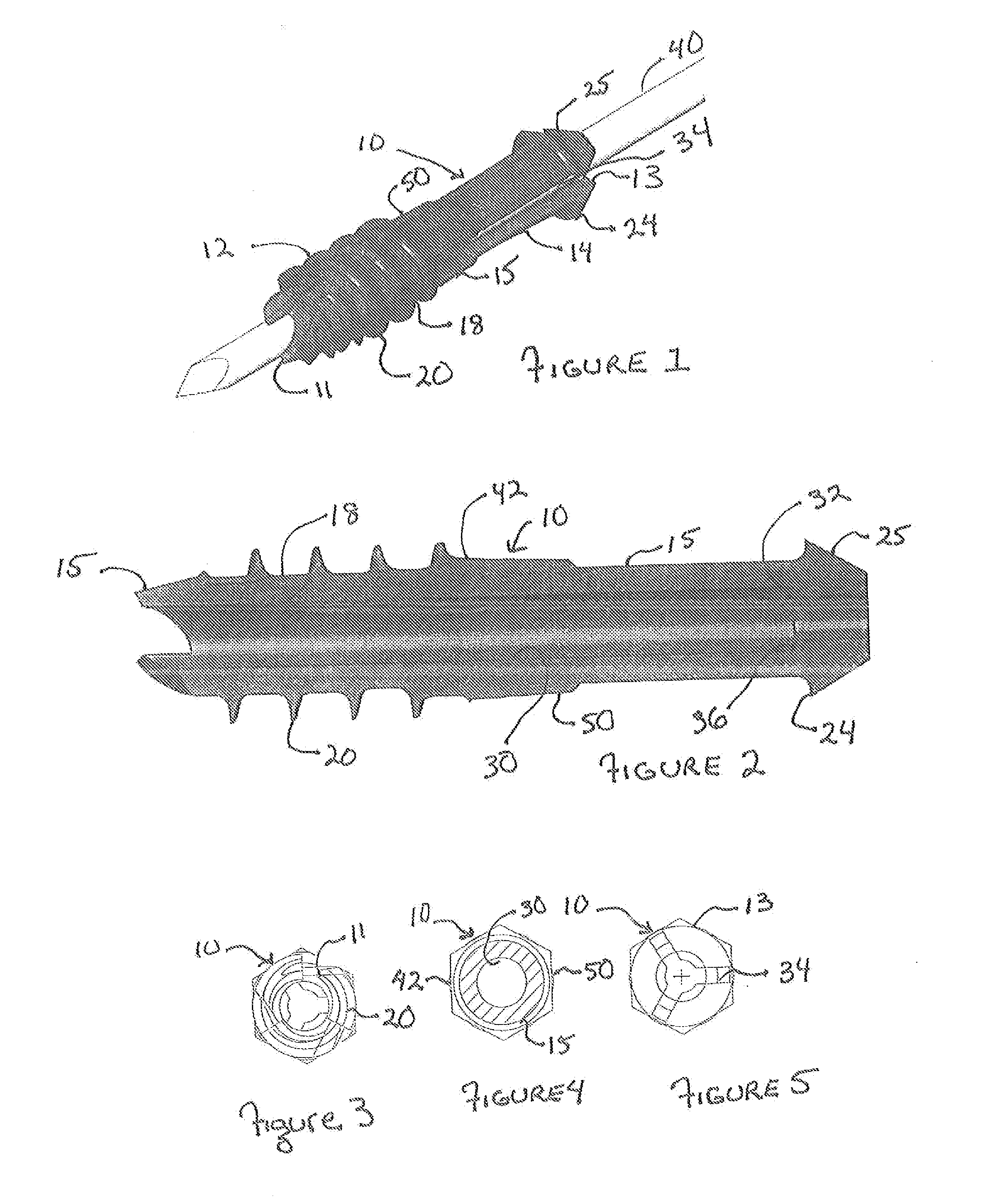
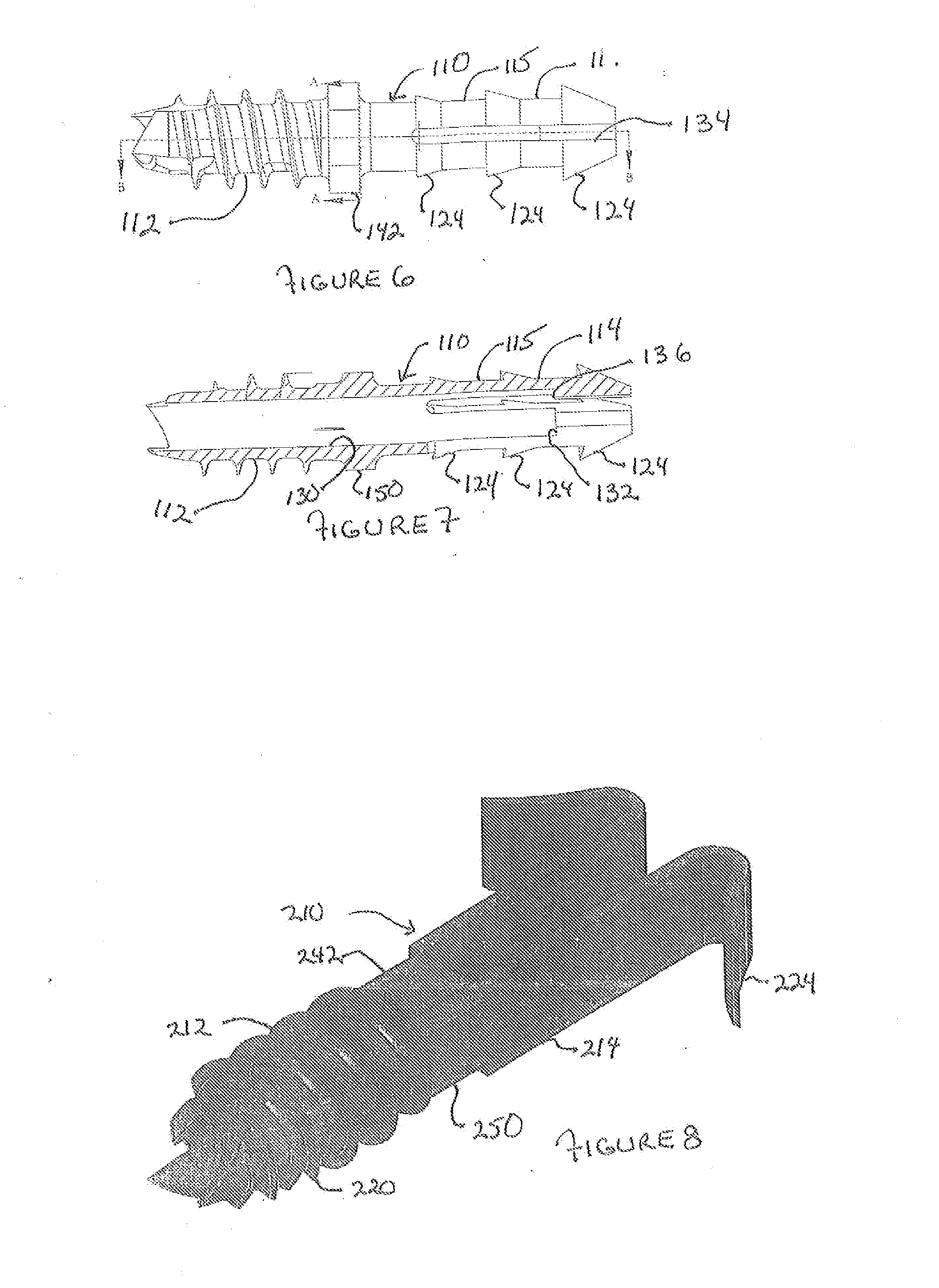
[0033]The second end section of the invention 14 includes anchoring means, and more specifically barbs or ratchets 24 extending away from a cylindrical base 23 having a minor diameter of 0.07 inch, where the barbs can include one or more conical sections 25 joined by a edge to the base to form a sharp edge 26 and the conical sections having a length along the longitudinal axis of from about 0.03 to about 0.08 inch. The conical sections include side extending surfaces which preferably form a radial and / or longitudinal portion of a cone or a geometrical construct that expands radially like a cone but is constructed of flat surfaces. In the embodiment of the invention illustrated in FIGS. 6 and 7, the implant 110 includes a second end section 114 having three barbed sections 124 of increasing size, having a length in a first barb section of 0.07 inch and a diameter of 0.126 inch for the larger implant (a length of 0.05 and a diameter of about 0.08 for the small implant and a length of ...

third embodiment

[0034]FIG. 8 illustrates the implant of the invention 210 having a first end section 212 with threads 220 and a second end section 214 with flexible anchoring wings 224 that act to anchor the implant in the smaller pre-drilled hole in the second section of bone. The purpose of the barbed section of the implant is to define a relationship with a second bone segment so that the anchoring members 24 (124,224) expand and lodge within the second section of bone.

[0035]Further, the implant 10 (110, 210) optionally includes a cannulation 30 (130) aligned with the longitudinal axis (i.e. co-axial therewith) coupled with expansion means 32 (132) which permit the second end section 14 (114) of implant 10 (110) to expand radially. In the embodiment shown in FIGS. 1-5, for example, the expansion means comprises the conical sections 24 described above and the second end section 14 further has one or more, and preferably two or more radially spaced expansion slots 34 which run parallel to the long...

first embodiment

[0036]Preferably, the implant 10 (110, 210) also includes a collar 50 (150, 250) having a length of about 0.050+ / −0.005 inch intermediate to the first end section 12 and the second end section 14 which includes one or more, (and preferably from about 3 to about 8) radially flat exterior surfaces 42 (142, 242) to allow the first end section to be screwed into a first bone section. Advantageously, this collar defines a hexagonal torque-driving surface. The implant is made from a suitable biocompatible material, for example, such as medical grade stainless, titanium or titanium alloy, nitinol, ceramic or PEEK or similar implantable polymeric material. Optionally, the guide wire may include means to avoid infection, such as an antimicrobial treatment and / or a cap at the wound site.

[0037]FIGS. 13-15 illustrate a third embodiment of the invention in which the implant 310 includes the threaded first section 312 joined to the barbed second section 314 but in which the second section 314 is ...


PUM


Abstract

The invention comprises an implant having a first end section and a second end section, where the first end has a cancellous thread for implantation in a first section of bone and the second end includes expansion slots and barbs or wings, that that resist movement out of a second section of bone. These anchors expand outwardly when a rigid wire, such as a k-wire is fed through a central cannulation in the implant and either the wire expands in diameter or the cannulation decreases in diameter. The implant also includes a collar intermediate to the first and second section which includes one or more surfaces to allow the first section to be screwed into a first bone section.

Description

FIELD OF THE INVENTION[0001]This invention relates to a generally cylindrical intramedullary implant, that is threaded at one end and barbed at the other, for use in joining a bone to another object, including another bone, such as an opposing phalange in a hammertoe procedure. It can also be used for corrections of imbalances in the fingers, and for dental implants. It relates as well to a method of performing procedures for the correction of hammertoe or for trigger finger wherein the implant is threaded into a first phalange and anchored in an adjacent phalange using a guide wire, which activates a mechanism to deploy the barbs into the surrounding bone.BACKGROUND OF THE INVENTION[0002]The present invention relates generally to orthopedic implants for use in a joint fusion (including fibrous union or even non-union), or as a post for use in a dental procedure. In particular, the implant of the present invention relates to an interphalangeal fusion implant which provides for a sta...

Claims


Application Information

Patent Timeline
Patent Type & Authority Applications(United States)
IPC IPC(8): A61F2/46A61F2/42
CPCA61F2/4606A61F2/4225A61F2002/4228A61B17/68A61B17/7258A61B17/848A61B17/8625A61B17/864A61B17/8872A61B17/8897A61B17/7291A61B17/17A61B17/7266
Inventor LEWIS, DEREK S.MARTIN, AMANDA M.PRICE, JAMES P.ZWOLINSKI, MICHAEL A.KAY, DAVID B.
Owner ORTHOHELIX SURGICAL DESIGNS
Why Eureka
Try Eureka